|
Making a Van Leeuwenhoek Microscope Lens by Hans Loncke, the Netherlands |
|
About 50 years ago, as a budding aircraft instrument maker, I learned, quite professionally, the craft of making optical elements, lenses, prisms and mirrors, all in my spare time. I had the opportunity to do that one evening every week for twelve years. At the end of this period, the art of lens grinding had onlya few secrets for me. During that time I always made ‘large’ optical elements, Newton telescopes, tele camera lenses, magnifiers, roof prisms etc., things that I was eager to have but not able to buy. I never made tiny things such as those van Leeuwenhoek lenses; I had no goal for that stuff. Last year, after 50 years of intensive and not always careful use, my two Steinheil magnifiers (achromatic triplets) were too much scratched to be used with pleasure. At last, there was only one solution for the problem: I had to repolish them. But now I had no truing tools, no polishing tools, and no optical measuring tools. However, I knew what was needed. I took the triplet out of its holder, cleaned the circumference and glued it with a warm balsam into a brass sleeve, one scratched convex surface poking out just enough to be worked on, taking precautions to prevent abrasives sneaking in. On my lathe I made a close fitting true tool, the exact radius was carefully made with a scraper. Truing the lens surface was done using number 400 abrasive and water and in 25 minutes all the scratches were gone and the surface had a fine frosted finish. I checked for pits using a 10x magnifier, a sharp light and black background. This to prevent a too long a time polishing. I could not find the good old black polishing pitch so I used thin leather stuck on a fitting aluminium holder as a polisher tool. Polishing with leather (or felt) produces an orange-peel surface on the glass, visible only under a 10x magnifier. Not the finest possible surface but in this case good enough for me. A few hours later, the other side of the magnifier was handled the same way and so was the second magnifier. My old drilling machine on ’very slow’ speed was the driving force; white cerium oxide was the polishing material. |
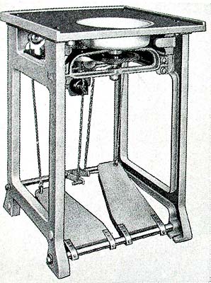
fig. 1 |
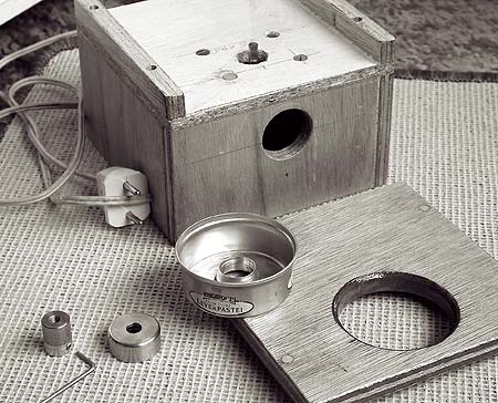
fig. 2 |
The improvising and thinking ’how to proceed next’ took much more time than the work itself. Interested in working with microscopes for only 30 years I then thought about making a small lens, small enough to be used in a microscope like the ones Antoni van Leeuwenhoek made. Would it be possible? I never made a lens that small before, had no use for it. What problems would it present to me? I decided to take the chance. For this small lens I choose a 3 mm radius for both sides and 1 to 2 mm thickness. If successful, it would result in an approx. 60 to 70 x magnification. Let’s try to see if it works.
My drilling machine appeared a little too
noisy so another grinding and polishing
machine had to be constructed. Fifty years
ago my favourite grinding and polishing
apparatus was a 20th century treadle
machine (fig. 1). Antoni van Leeuwenhoek
also used a treadle machine with a
vertical spindle; I presume it was a too
and fro rotating one. Driven by foot power
it could well have run at 400 rpm. |
|
Then I made adapter fittings to hold the
grinder and polisher tools. To prevent spent
water and abrasives access to the bearings I
improvised a trough from a liver pie tin
(fig.3). All this worked satisfactorily except
for the motor getting very hot. After reducing
the power voltage to 130V with a variable
transformer and making vent openings in the
box I had no more heat problems. The spindle
rotates left-hand at about 250 rpm.
|
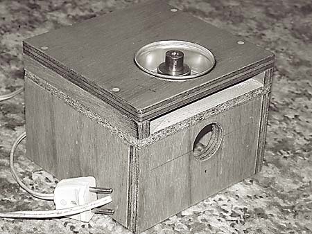
fig. 3 |
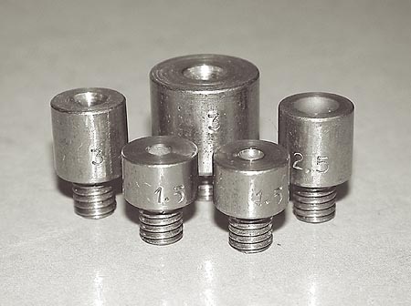
fig. 4 |
Of which material shall I make the grinder
tools? |
|
Next question was: what kind of glass will I use? What kind of glass may van Leeuwenhoek have used? Would he have used an old bottle or a broken Venetian drinking glass? A broken spectacle glass or a broken windowpane? After the 1654 powder house explosion in Delft (80.000 pounds of black powder went bang) there must have been thousands of broken window panes, he will surely have found enough glass, good enough to be used for his lenses. I think he had not much choice. Neither had I. Of course I would rather have chosen for some excellent clear optical glass, but that possibility had long vanished. I took an empty jam-jar and smashed it with a hammer (fig. 5). |
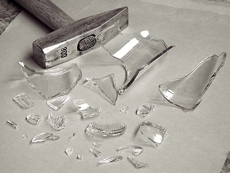
fig. 5 |
|
This glass surely was better than the glass that van Leeuwenhoek had used. Handling such small sharp fragments is not practical so I selected a handful and cemented them onto 10 cm long and 3 to 4 mm thick plant-sticks (fig. 6) with warm balsam. Van Leeuwenhoek will have done the same. |
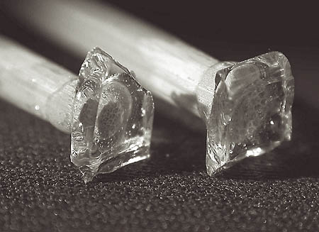
fig. 6 |
|
|
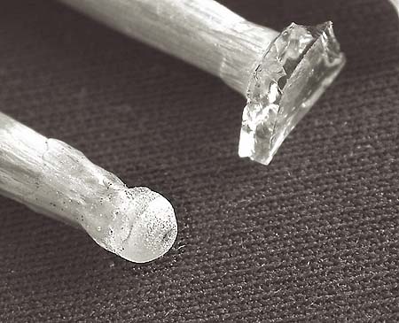
fig. 7 |
I started grinding the pieces by hand into a
more or less cylindrical shape of 3 to 4
millimetre diameter. This was done on an
A4-size piece of window glass, using nr.120
grinding abrasive. Next, I ground a roughly 3
mm convex radius (fig. 7).
|
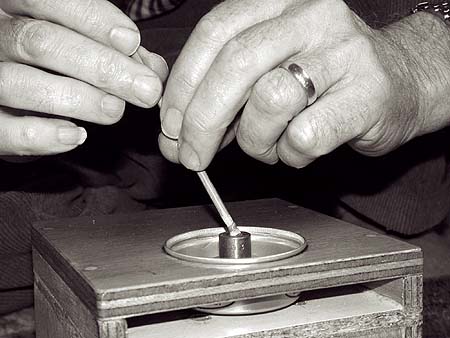
fig. 8 |
Then I screwed the steel grinder tool
(radius 3 mm) onto the shaft of the
grinding- machine and ground the first
side of the glass on the stick (fig.8)
with abrasives nr. 220 to 360 till it had
an even frosted surface. At each change of
grain, the tool, lens and working area
must be thoroughly rinsed in easy running
water to prevent the lens from being
scratched by one left coarse grain. It
appeared very useful to put the plug into
the sinkhole . . . . |
fig. 9 |
Next operation was the polishing. This time I had no trust in polishing with leather or felt, as a tiny lens like this with orange-peel surface will certainly not produce a sharp image. Leather or felt are too soft polishing material, they will follow the smallest unevenness on the surface of the glass instead of removing it. I needed a more sturdy polisher surface. Here history came to help. Over 50 years ago, my classmates and I (aircraft- instrument-makers to be) were on an excursion at Schiphol Airport where we visited the flight instruments verification and repair-department. In there, I noticed a person who was polishing the pivot end of the gyroscope of a course indicator (an extremely delicate flight instrument). The polishing was done with a pre-shaped piece of hard wood, to be precise of ironwood (Guayacum-wood). This ironwood is very hard, it has a very fine grain and when used as a polisher tool, will take away the smallest unevenness of a steel or glass surface. I have no ironwood, neither boxwood but beechwood is another fine grain rather hard wood. So I made a polisher tool of beechwood (fig.9), screwed it onto the shaft of the grinding-machine and polished an excellent smooth surface on my lens. During polishing the stick-and-lens must be regularly rotated (against the tool rotation) and oscillated to and fro to achieve the best possible uniform spherical shape. When polishing was finished I checked for pits with a 10x magnifier under sharp light. When no pits were visible under a 10x magnifier, the lens was taken off the plant-stick and cleaned with acetone. |
|
Before working the other side, first
this: |
fig. 10 |
|
I did change the plant-stick for a 3,5 mm diam. aluminium stick. I made a centred hollow in the aluminium stick, this makes centred cementing of the lens easier. I cemented the lens in reverse position with warm balsam onto the aluminium stick again. The second surface is worked on the same way as is the first. I grind with abrasive nr.220 and 360 until the circumferences of both sides of the lens meet completely and form a sharp rim together instead of the cylinder. Here is some risk that flaking may occur, i.e. that flat splinters can break out on the polished side. To prevent this a facet must be provided, so I held the lens on the stick between wet waterproof emery paper nr. 400 (or up) and rotated the stick for about half a minute to grind the sharp rim down to a facet of about 0,3 mm (fig.10). This makes the lens diameter a little smaller but that is no problem. After cleaning, the lens was further trued with emery nr.400 until the surface was completely fine frosted. After the check for pits, polishing was done. When the lens was completely polished and no pits were visible under the 10x magnifier, it was loosened from the stick and cleaned with acetone. To be sure I made not one but four lenses (fig.11). |
fig. 11 |
fig. 12 |
Then a quality check had to be made and I
want to know the focal length and
magnification. Fig.12 gives the set-up. Use a microscope with a x 10 lens, remove the condenser and put a clean slide on the stage. Put a measuring eyepiece into the tube and calibrate it with an object micrometer or any other suitable scale. Make a note of the distance between two scale-divisions. |
|
Remove the object micrometer and put the lens-under-test on the slide right below the x 10 lens. Set up an illuminator, stick the test-target (fig.13) on it and move it to a distance A (lens to mirror) plus B (mirror to test-target) = 250 mm from the lens-under-test. That 250 mm is the normal reading distance and is accepted as the standard distance. Aim the light beam to the centre of the mirror. Aim the mirror in such a way that lens-under-test is in the middle of the light beam. Look through the microscope, find the image that the lens-under-test makes and focus on it. Measure the image of the test-target and compare it with the image of the original. |
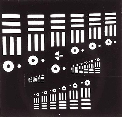
fig. 13 |
|
Example: It’s as simple as that ! |
|
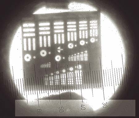
fig. 14 |
In fig.14, it is clear that the black and white contrast is less than on the original test-target. The cause is in the spherical aberration of the lens-under-test, which is very high because the lens is viewed with full opening 1 : 1. Built into a Leeuwenhoek microscope the lens will be stopped to 1 : 4 and then will produce a much higher contrast. |
All comments to the author Hans Loncke are Welcomed
Microscopy UK Front
Page
Micscape Magazine
Article Library
all material © Hans Loncke