An Electronic Flash Illumination System for
Photomicrography
by Ron Neumeyer
The system described in this article consists
of an external illuminator linked by fibre optic cable to the
microscope lamp house. There are several components; a light
source ("the box"), a fibre optic cable, a rheostat
controlled lamp power supply, a lamp adaptor and an electronic
flash. The 100 watt halogen bulb generates enough light for most
viewing applications, while the integrated flash produces razor
sharp, true colour images, regardless of subject movement or
instrument vibration.
The Box
 The
combining of light from the flash and halogen bulb takes place
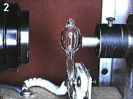
inside the "box". In reality the box is a standard
metal housing sold by electronic supply houses. Picture 2 shows
the inner workings of the box. The spectacle lens on the left
side of the picture collects and focuses the flash pulse onto the
receiving end of the fibre optic cable, the small metal tube
almost touching the surface of the bulb.
The
combining of light from the flash and halogen bulb takes place
inside the "box". In reality the box is a standard
metal housing sold by electronic supply houses. Picture 2 shows
the inner workings of the box. The spectacle lens on the left
side of the picture collects and focuses the flash pulse onto the
receiving end of the fibre optic cable, the small metal tube
almost touching the surface of the bulb.
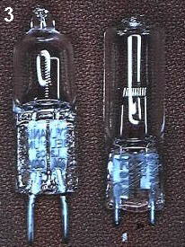
 The halogen bulb
is located between the cable end and the condenser. I use a
general purpose bulb, available from most hardware stores. The
reason for selecting this type, rather than one designed for
microscope use, relates to filament configuration. Most
microscope bulbs have a flattened coil filament orientated left
to right (right of Picture 3) which prevents the flash beam from
reaching the cable. On the other hand, the general purpose bulbs
have cylindrical filaments aligned from top to bottom, with
widely spaced coils (left of Picture 3). This pattern allows the
flash burst to enter the cable end, essentially unobstructed.
The halogen bulb
is located between the cable end and the condenser. I use a
general purpose bulb, available from most hardware stores. The
reason for selecting this type, rather than one designed for
microscope use, relates to filament configuration. Most
microscope bulbs have a flattened coil filament orientated left
to right (right of Picture 3) which prevents the flash beam from
reaching the cable. On the other hand, the general purpose bulbs
have cylindrical filaments aligned from top to bottom, with
widely spaced coils (left of Picture 3). This pattern allows the
flash burst to enter the cable end, essentially unobstructed.
 A 110
volt cooling fan is bolted to the inside of the box, opposite the
bulb (available from computer or electronic supply houses), a pin
base for the bulb is fastened to the bottom, and a metal sleeve
for holding the cable in position passes through the end plate
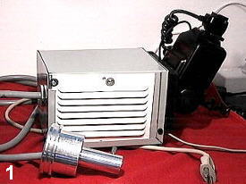
(dark coloured tube on the right of Picture 2). The fan draws air
through an intake grill (Picture 1) directing it across the bulb
and out on the opposite side through an exhaust grill. (A cooling
fan must be installed with 100 watt-plus bulbs as they release a
great deal of heat, especially when run at full capacity.)
A 110
volt cooling fan is bolted to the inside of the box, opposite the
bulb (available from computer or electronic supply houses), a pin
base for the bulb is fastened to the bottom, and a metal sleeve
for holding the cable in position passes through the end plate
(dark coloured tube on the right of Picture 2). The fan draws air
through an intake grill (Picture 1) directing it across the bulb
and out on the opposite side through an exhaust grill. (A cooling
fan must be installed with 100 watt-plus bulbs as they release a
great deal of heat, especially when run at full capacity.)
Also visible in Picture 1 is the grey fibre
optic cable connected to the box at one end, and the adaptor
(described later) at the other . This particular cable is very
flexible, rather like heavy gauge electrical cord. The plug and
cord in the lower right connects the bulb to a 12 volt
transformer (following section). The 300TL flash can be seen
entering the back of the box. The grey wire coming from the lower
left corner is the power cord for the fan (110-volt).
Lamp power supply
In Canada, building supply stores now stock a
good selection of small, 12 volt transformers used to power
general purpose halogen lighting. I use one to power my lamp. It
can handle 150 watts and is about the size of a pocket flash
light. Light output can be controlled by installing a household
dimmer-switch between the house power source and the transformer.
I have installed the transformer and output control in a separate
housing as I am using a large mechanical dimmer to avoid
electronic noise when using a video camera.
Bulb Assembly Adaptor
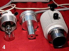 The
bulb's socket assembly must come out in one piece in order to
machine the cable adaptor. The aluminum adaptor is made to have
the same outside diameter as the socket assembly. This allows the
cable to be positioned where the bulb filament would normally
sit. How this was done for the 250 lamp house is shown in Picture
4. On the left hand is the bulb and socket assembly, which fits
snugly inside the lamp house, and visible on the far right. In
the centre of the picture is the machined adaptor holding the
fibre optic cable. The cable can be seen entering the device at
the top of the picture. It passes through a hole drilled in the
adaptor to match the its outside diameter. The output end of the
cable is located at the end of the adaptor's "snout".
The
bulb's socket assembly must come out in one piece in order to
machine the cable adaptor. The aluminum adaptor is made to have
the same outside diameter as the socket assembly. This allows the
cable to be positioned where the bulb filament would normally
sit. How this was done for the 250 lamp house is shown in Picture
4. On the left hand is the bulb and socket assembly, which fits
snugly inside the lamp house, and visible on the far right. In
the centre of the picture is the machined adaptor holding the
fibre optic cable. The cable can be seen entering the device at
the top of the picture. It passes through a hole drilled in the
adaptor to match the its outside diameter. The output end of the
cable is located at the end of the adaptor's "snout".
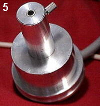 A
close up view is shown in Picture 5 ( circular object in the
centre is the cable end).
A
close up view is shown in Picture 5 ( circular object in the
centre is the cable end).
The adaptor is inserted into the lamp house so
that the tip of the cable is located at the same point as the
filament of the original bulb (the adaptor can be adjusted in the
same manner as the bulb socket). A threaded set screw locks the
cable in the adaptor (knob in Picture 5).
Flash
The head of the flash fits into an opening at
the back of the box, with its Fresnel diffuser located near the
focal plane of the spectacle condenser. The flat surface of the
condenser faces the bulb, opposite the fibre optic cable (shown
in Picture 2). Internal reflection conducts any light beam along
the inside of the cable to the lamp house, where it enters the
normal light path of the microscope.
The flash light pulse enters the fibre optic
cable at the same point as light from the bulb. In other words,
the pulse becomes part of the light energy carried along the
cable. However, as its intensity is much greater then a 100 watt
bulb, and with shutter speeds of 1/60 second or shorter, the
pulse, not the bulb, imprints the image on the film emulsion.
Light from the bulb, especially when dimmed slightly, does not
take part in image formation. In fact, exposure time is
determined entirely by flash duration (1/700 to 1/10,000 of a
second), not shutter speed. As a result most moving objects can
be captured without blur, and vibrations caused by the shutter
will not effect in the picture. In addition, because the flash
delivers light very similar to daylight the photographer can use
any daylight balanced film without corrective filters.
Conclusion
Hopefully I have provided enough background
detail to get you started on building a similar system for your
microscope and camera. It may take some tinkering, but believe me
it is worth the effort! Before closing I should point out that
box-cable flash system can be used on different scopes, all that
you need do is machine new adaptors. In fact, the cable alone can
be used alone to illuminate objects viewed by reflected light,
such as when using a stereo microscope. That about wraps it up,
however if you need help, or have questions, do not hesitate to
contact me by Email. If need be I can send
JPEGs of specific components.
Ron Neumeyer
11135 Kendale Way,
North Delta, British Columbia
V4C 3P7
Canada
© Microscopy UK or their
contributors.
Please report any Web problems
or offer general comments to the Micscape Editor,
via the contact on current Micscape Index.
Micscape is the on-line monthly
magazine of the Microscopy UK web
site at Microscopy-UK
WIDTH=1
© Onview.net Ltd, Microscopy-UK, and all contributors 1995 onwards. All rights
reserved. Main site is at www.microscopy-uk.org.uk with full mirror at www.microscopy-uk.net.