|
by Ted Clarke, USA
|
Most images are clickable to view a larger version.
My work experience as a ferrous metallurgist in the farm and construction equipment industry required almost daily use of the stereo microscope and the metallurgical microscope. Imaging at work was done on 4 X 5 Polaroid film, until the transition in 1995 to high-resolution digital imaging using a MegaPlus 1.6i/AB monochrome camera. Downsizing in the early 1980s led to my learning to do much of my own metallographic imaging with a Zeiss Ultraphot II. I also had to do my own photomacrography, leading me to derive, at home, the equations to optimize depth of field while still maintaining high resolution. I built a 35 mm camera system in my home machine shop for experimental testing of the equations. This led to my purchasing the full complement of Olympus bellows lenses and their attachments for vertical illumination of mirror-like flat surfaces. The Zeiss Ultraphot has a photomacrography system using the Luminar lenses. These macro lenses have vertical illuminators which we used for photomacrography of field sizes larger than could be recorded with the 4X 0.10 NA metallurgical objective. The lowest magnification with the 100 mm Luminar in reflected brightfield is 6.5 X on a 4 X 5 Polaroid film print. A larger field size at lower magnifications was often desirable for imaging metallographic specimens, but not available with the Ultraphot. The Leitz Aristophot of the early 1960s had a system for recording a complete 37 mm diameter metallographic sample with reflected brightfield illumination. I decided to design and build a photomacrography system at home with this capability. More recently, my wife wanted a microscope with polarized light capability for artistic imaging of birefringent crystals, with compensators to vary the interference colors. This resulted in my building at home a universal student microscope with reflected brightfield capability so that I could examine metallographic specimens. My preparation for this article included reading portions of Cyril Stanley Smiths A History of Metallography where I learned more detail about Henry Clifton Sorby, an amateur scientist who founded and further developed the field of metallography between 1863 and 1887 while working in a home laboratory. He prepared thin sections of opaque metal mounted to slides. He learned to polish the surfaces without leaving a layer of flowed metal, and how to etch the properly polished surfaces with dilute nitric acid to reveal their microstructure. He demonstrated that iron and steel were deformable crystalline solids with microstructures associated with their elemental compositions and metallurgical processing. These discoveries made with reflected light microscopy greatly hastened the development of the industrial age, and were the basis for the modern field of materials science and engineering.
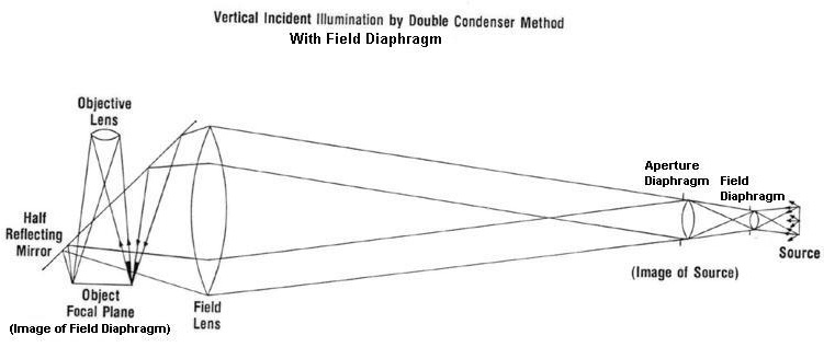
Fig. 1 The operating ray diagram for my reflected brightfield illumination systems is shown in Figure 1. The Olympus mirror housings for their macro lenses contain a half-silvered beam splitter with a field lens on the side. I use a double condenser illuminator composed of slide mounted camera lenses, with the end of a fiber-optic light guide as the light source. The iris diaphragms in the camera lenses of the double condenser system become the field and aperture diaphragms. The aperture diaphragm of the illumination system is imaged in the aperture of the macro lens recording the specimen field, as is customary with the Leitz Aristophot, Nikon Multiphot etc. The use of the fiber-optic light source and the imaged field diaphragm, as in Koehler illumination, is unconventional.

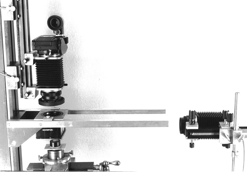
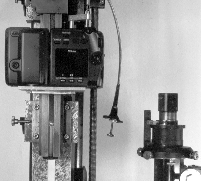
Fig. 2

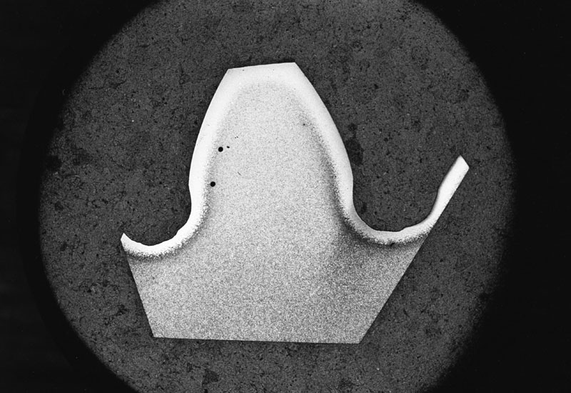
Fig. 3Figure 2 shows my 35 mm camera system used to record in reflected brightfield illumination the complete metallurgical section of an etched gear tooth shown in Figure 3. This was done with the Olympus 80 mm macro lens with a camera magnification of 0.7X. The black dots on the left side of the tooth are hardness tester indentations spaced 2 mm apart as a size reference.
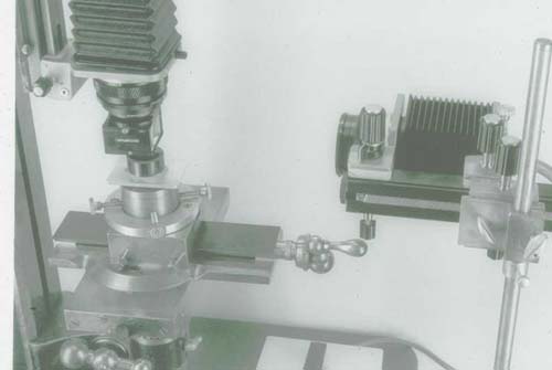
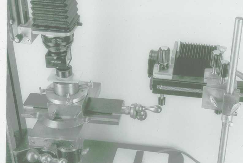
Fig. 4

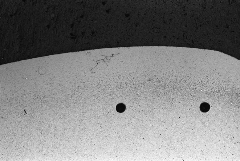
Fig. 5
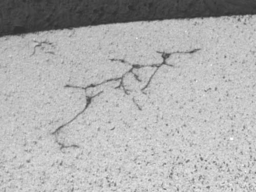
Fig. 6The 38 mm Olympus macro lens and mirror housing shown in Figure 4 were used to record a portion of the gear tooth specimen shown in Figure 5. The camera magnification was 6X and the aperture set at f/4 for an intended 8X enlargement in printing to meet an Abbe criterion of final magnification equal to 500 times the numerical aperture. A high-resolution portion of this image in Figure 6 shows in more detail a near surface crack pattern of contact fatigue cracking from transmitting load to the mating gear teeth. The white, outer portion of the gear tooth in Figure 3 is the high-hardness, lightly-tempered zone enriched with carbon during the carburizing heat treatment. This layer appears almost as dark as the black mounting material, and the low carbon core of the tooth appears brighter when the same sample is illuminated from the side, as in darkfield. Sorby was the first person to realize the difference between reflected darkfield and reflected brightfield, and the advantage of having both types of illumination for examining his steel and iron microstructures. His early experiments were with the light introduced below the objective from a 45° angle reflector or thin plane-glass reflector. This method works well through the 10X objective. Higher power objectives have short working distance requiring the illumination to be introduced above the objective, with the objective acting as its own condenser.

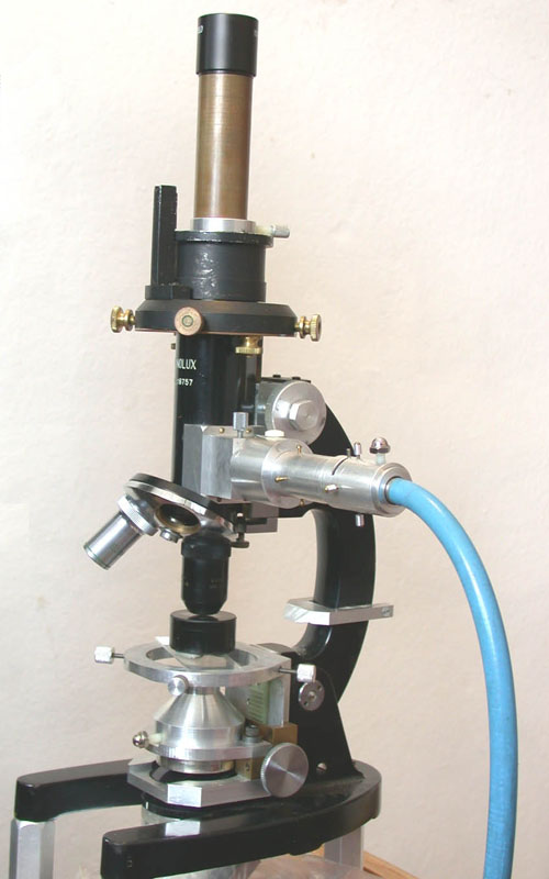
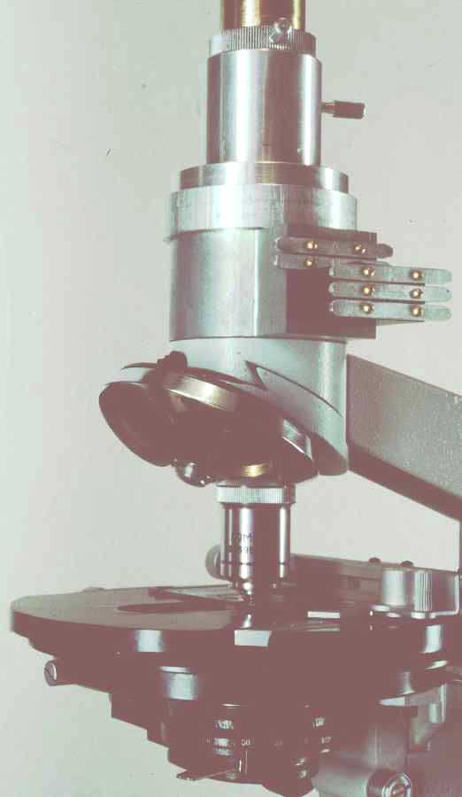
Fig. 7By 1887 Sorby had an improved vertical illuminator, which made possible his high magnification imaging showing that pearlite microstructure in steel and cast iron consists of alternating layers of iron carbide and low carbon iron. His reflector most probably was a thin, 45 degree oriented, plane-glass beam splitter located above the objective. This is the microstructure I used for evaluating the homebuilt vertical illuminator for my modified Monolux microscope shown in Figure 7.
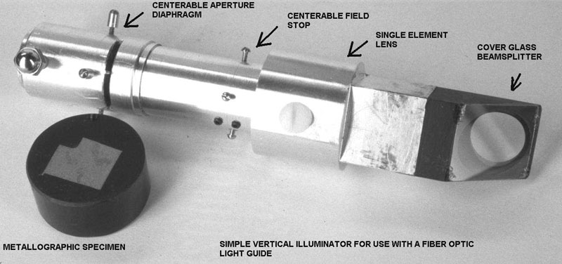
Fig. 8
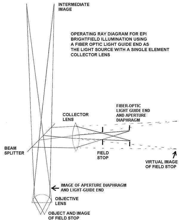
Fig. 9Figure 8 shows the vertical illuminator along with the metallurgical specimen of gray cast iron used for testing the imaging system. The use of a fiber-optic light-guide end as the light source allows a very simple illuminator design. The operating ray diagram is shown in Figure 9. A conventional vertical illuminator contains three lenses whereas my design only requires a single-element lens. The use of a fiber-optic source allows this simple design because the aperture diaphragm can be located at the light source rather than at an image of the source. Other advantages of using the fiber-optic light source are its high light intensity, making the 10% reflecting efficiency of the cover glass beam splitter quite adequate, and the heat from the 150 watt illuminator kept far away from the optics. The rotating stage had to be removed to obtain adequate working room for the metallurgical mount, which is leveled with modeling clay on a glass slide.
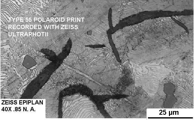
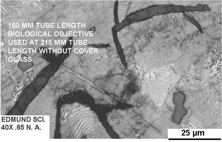
I have a set of Bausch & Lomb 215 mm tube length metallurgical objectives that can be used on the modified Monolux. The drawtube allows setting the tube length between 150 and 215 mm. My initial testing started with using a Zeiss Ultraphot and Epiplan 40X 0.85 NA objective to record a sample field at 500X on Polaroid Type 55 film print. This same field was then located with the modified Monolux using the 50X 0.85 NA Bausch and Lomb objective. I could not detect any difference in resolution or contrast. So I next tried using a 170 mm tube length 40X 0.65 NA Edmund Scientific JIS biological objective at 215 mm tube length to compensate for use without a cover glass. I was surprised to obtain adequate image quality. The Zeiss objective has a higher NA, which accounts for the finer pearlite lamella spacing resolved with this objective versus the biological objective. This can be seen in a comparison of Figure 10 with Figure 11.

Fig. 10

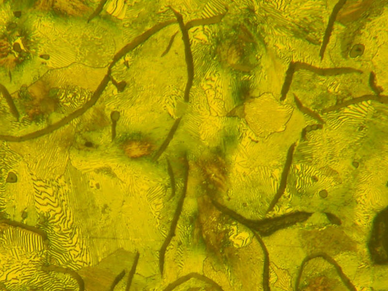
Fig. 11I have done recent testing for this article using the same gray iron specimen with the object of seeing whether high school and home microscopy of metallurgical specimens is feasible using a biological microscope equipped with a vertical illuminator as I have done. Industrial laboratories could be a good source for interesting specimens for high school students and amateur microscopists to examine. Older specimens are normally discarded. The problem with steel and iron samples is protecting the etched surfaces from corrosion and finger print damage. The answer to this concern came from reading about Sorbys pioneering work. Sorby prepared thin sections of metal with cover glasses bonded to the etched surfaces with Canada balsam. These specimens are in excellent condition after over 100 years of storage. Sorby had to use a biological microscope for his work because a metallurgical microscope did not exist then. The biological objectives are corrected for spherical aberration when used with cover glasses. Metallurgists have been taught that they should not use a cover glass because the reflection from the air-glass interface will seriously degrade the image contrast. I decided to see how bad this contrast loss would be by imaging the gray iron specimen using the 215 mm tube length 20X 0.40 NA metallurgical objective without a cover glass for Figure 12. I then used Canada balsam to bond a cover glass to the specimen and imaged it at 170 mm tube length with a 20X 0.40 NA JIS biological objective for Figure 13.
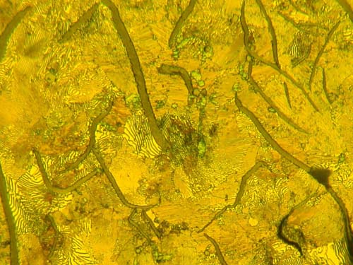
Fig. 12

Fig. 13The loss in contrast caused by the cover glass is apparent, but the image is still useable. I have not converted these images to grayscale because they show that a yellow-green filter was used, as is standard practice for metallography with achromatic objectives corrected for spherical aberration at this wavelength. The loss in image contrast, from reflection at the air-glass interface due to the cover glass, can be prevented by using an oil immersion objective. Oil immersion objectives are commonly used by biologists, but unfortunately not often used by metallurgists and materials scientists. I decided the next experiment would be with a 90X 1.25 NA LOMO oil immersion biological objective at its correct tube length of 160 mm to see if the contrast loss could be prevented. This objective requires use of a compensating eyepiece. A Zeiss 12.5X kpl eyepiece was used with the 90X LOMO objective to record the image that is shown in Figure 14. The image contrast is very good. This image shows loss in detail towards its edges due to field curvature, which can be expected because the objective is not a planachromat. Recording this image was difficult because the fine focus in the Monolux is not very precise and stable. It was difficult to keep the microscope in focus while sliding it under the Coolpix 995 digital camera shown in Figure 15.
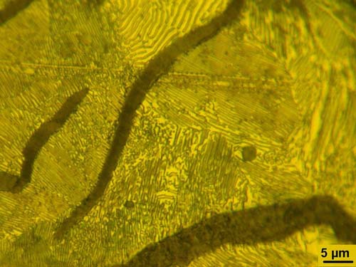
Fig. 14

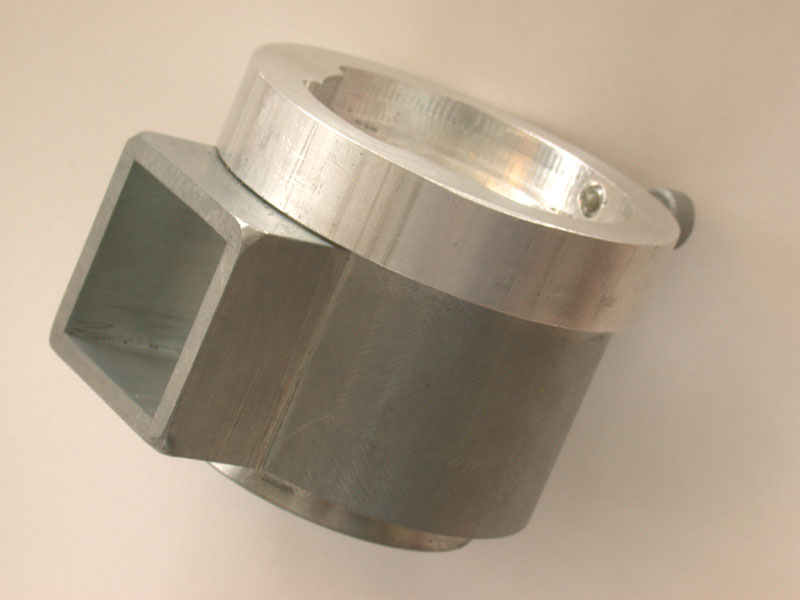
Fig. 15I would have much preferred using my Biolam student microscope with its trinocular head for this final experiment. Unfortunately, I have not had time to make a vertical illuminator for the Biolam. This microscope has rotary dovetails to attach the viewing heads to the limb. I made the male and female dovetail ended housing shown in Figure 16 to hold slider mounted compensators and the analyzer as shown in Figure 17. This housing was designed to hold a vertical illuminator like that made for the Monolux.
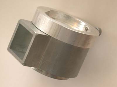
Fig. 16
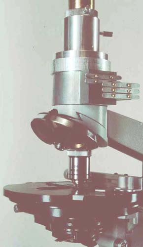
Fig. 17All comments to the author Ted Clarke are welcomed.
Reference:
Clarke, T. M. Vertical Incident Illumination for Photomacrography; The Microscope 1988, 36, 11-34.
Please report any Web problems or offer general comments to the Micscape Editor.
Micscape is the on-line monthly magazine of the Microscopy UK website at Microscopy-UK