 |
| Preservation of Contrast
in the Compound Microscope (Part 1)
A personal perspective concerning errant light : its origins and effects on imagery By Paul James |
Soon after I became familiar with my first microscope, I noticed when reinserting the eyepiece that the internal surface of the drawtube was sufficiently polished to reflect light that found its way off axis and thence reflected back into the aerial image. This simple but surprising revelation, that light does not always behave and keep to the pathways of ray diagrams was easily remedied by inserting a 'cylinder' of dark fabric into the drawtube. A salutory lesson of course which slowly ensconced its way into my subconscious as well as awakening my youthful view of things mechanical and reinforcing the paradox between theory and reality.
That simple experience raised my level of awareness, and so I thought that if a simple remedy could improve imagery then surely there must be other ways of doing so? This was a little naive on my part in those early days but there was some truth in that premise, though most of the problems attending microscope design were obviously over my head at that time. Despite the passing of years, I still took for granted that manufacturers of microscopes had dealt with all things technical, and therefore I reasoned that little improvement in their imagery could be forthcoming, apart from the necessity for skilful manipulation of the instrument to realise its full potential. Yet there are differences in the makers' attempts to handle the intrinsic problems, particularly below the stage, where the generation of light occurs and where strict attention to design appears to be critical for the formation of a good image?
Kohler or Critical illumination is essential for quality imaging in Bright Field, a subject which has been well documented in Micscape already, but there is a rather important aspect of microscopy which is rarely given an airing: The preservation of contrast. There are many articles written about the contrast enhancing techniques of Phase Contrast, DIC, DF, COL, Oblique etc but very few are concerned with the problem of the intrinsic generation of light scatter or glare within the microscope during its passage through the labyrinth of glassware and tubing in the instrument.
The Refractor and the Microscope
In order to emphasise the importance of contrast in image production I'll wander into telescope design for a moment as contrast preservation of the subject's incoming light is utterly pivotal in rendering of a first class high fidelity image, which has some parallels in microscopy. One fundamental difference concerning astronomical and microscopical observation is of course that the light intensity levels vary immensely, the former often having very low light levels with which to image with, compared with microscope imagery where there is usually a surfeit. Despite these differences, the science of projecting a quality aerial image for the observer to scrutinise, whether it be a planet or a living cell is crucial in a state of the art instrument. One of the most important requirements for first class imaging is the preservation of contrast, and for both disciplines this applies in equal measure.
A quality refractor telescope's objective will be housed in a tube which possesses a considerable number of circular baffles gradually diminishing in diameter, each commensurate with the diameter of the tapering light beam down the tube so as to block and absorb any stray light which has found its way in from off axis objects, and to reduce internal reflections to zero. The inside will be matt black for obvious reasons like a camera's internal chamber, and also the inclusion of an exterior 'hood' or dew shield helps prevent stray light from diluting the image contrast too.
It would seem to be perfectly natural to adopt similar measures with the compound microscope to reduce light scattering to an absolute minimum, so that the emerging aerial image from the eyepiece is ideally as free of unwanted contrast diluting light as possible.
There are fundamentally 4 areas in microscopy where errant light originates : 1) Uncoated optics 2) Poor substage design 3) Insufficient baffling 4) Spherical and chromatic artefacts in both the substage lamphouse condenser and substage condenser 5) Lack of careful manipulation of substage illumination.
Anti reflective coatings
Good optical components are coated with anti-reflective coatings of varying types to facilitate maximum light transmission and reduce contrast degrading light scatter within groups of elements to a minimum.
|
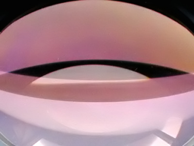
The image above is an oblique view of the surface of a high quality photographic reproduction lens. Despite the state of the art anti reflective coatings of the time we can easily see the purple light that this coating intrinsically reflects back albeit of small proportion. An uncoated lens would reflect much more than this, but if the coating was 100% effective we would not be able to see the lens's surface curves in this photo! This is not a criticism of anti reflective coatings but a vindication of how difficult it is to suppress unwanted light. Contemporary coatings are even more efficient again and tend to appear darker to the eye.
With uncoated optics which was universal in days gone by, the proportion of light scatter was intrinsically greater than is the case in microscopes of more modern times. There is little we can do with an older generation stand regarding this, as the cost of coating services which are available to the amateur will deter all but the most dedicated enthusiast. However, many a high quality microscope whose principal component glassware is coated may well have substage optics without coatings? Though I endorse the coating of objectives, eyepieces and any other relevant glassware including prism faces etc in binocular housings, there is a case for coating all the glassware below the stage too, though there remains some conjecture amongst microscopists about the effectiveness of this. I believe that because of the intensity of light generated in the lamphouse, special attention must be given to the baffling system especially as uncoated glass can generate errant light of considerable intensity.
Insufficient Baffling........Good design.........Lamphouse problems
A rather larger output of stray light is generated from the spherical aberration of many lamphouse condensers too, which is also often poorly baffled. Ideally the lamphouse condenser should be aplanatic ie, able to form an accurate representation of the source, but many 2 or 3 element lamphouse condensers are not fully aplanatic, generating a geometrically imperfect image of the source, sometimes grossly so. If the source is a diffusion faced element nearest the lamp filament, which is very common these days, then there is an added problem that the light passing from the diffuser source can scatter over a wider area even after passage through the blades of the field iris diaphragm's aperture, which is the principle controller of errant light from the substage. As long as this wayward light is absorbed by baffling and blacking of all relevant interior surfaces much less interference of the prime image's contrast will occur.
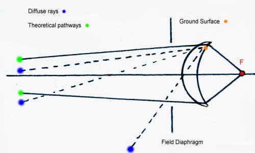 |
The principle purpose of frosting the first face of the lamphouse condenser shown above in simplified form, is to create an evenly illuminated field of view in the eyepiece. Frosted or ground glass does however scatter light very effectively over a considerable range of about 175 degrees! Three examples of such errant beams (and many more) radiate from a single point on the surface shown above, and will exist for every point on this surface despite the baffling capabilities of the field diaphragm. It is the less oblique rays of errant light that find their way into the substage condenser which can cause contrast diluting problems. Hence the desirability of a second field controlling iris, but this is the exception rather than the rule in mainstream microscopes. Ironically, the very technique of frosting the lamphouse condenser's face element, whose purpose it is to make an homogenous field of view, is the cause of another potentially image debilitating problem!
This second iris diaphragm is often sited immediately below the substage condenser in the base casting. The actual clear aperture of the opened iris of this secondary diaphragm acts as a baffle also, with further baffling as the iris aperture is reduced. The user must however be conversant with the basic geometry of the lighting pathways to take advantage of such a sophisticated illumination system as found on such stands as the Zeiss Photomicroscope etc.. The focussing of the lamp in such a setup is critical for best results.
Twixt Objective and Eyepiece
Above stage, design requirements are a little different. Here the light that emerges from the specimen is captured by the front element of the objective and is in various stages processed into an aerial image that issues forth eventually from the eyepiece. Baffling within objectives and eyepiece is usually well designed and implemented and so the vast proportion of light should pass through without causing any contrast dilution, especially with coated optical surfaces. The days when narrow internally polished drawtubes were commonplace is long gone together with their associated problems, and so I believe the upper section of the 'scope should have virtually no impact on contrast dilution save for the potential problems from the binocular/trinocular head which I'll raise further on.
User Assessment of contrast preservation
A rather simple but effective way of assessing your 'scope's contrast preservation capability is described below. It's merits are simplicity of use and can determine the presence of stray lighting in either the substage and or bino/trino heads, and therefore enables the user to identify a problem and hopefully rectify it.
Methodology
Employing a x 10 objective, setup brightfield with any thinly strewn specimen such as diatoms, butterfly scales etc.. Optimise all parameters for BF but leave both the field and condenser iris diaphragms fully open. Move the slide to clear the field of any specimens etc.. Now withdraw the head a centimeter or two away from the eyepiece(s) but still on optical axis. You will notice that the 'field' diminishes in diameter, but attention should be given to the 'annular' area around this which exists between the reduced field and the field baffle of the eyepiece. At first this is not an easy skill to accomplish until you know what to look for. You should perceive a dimly lit 'annulus' of light around the reduced field which is the culmination of all the stray lighting passing through your microscope. By leaving the field iris fully open you will have maximized stray lighting to its greatest intensity. Now by reducing the field iris's diaphragm whilst simultaneously observing the 'halo' in the eyepiece, you will notice a significant decrease in the intensity of the halo which is roughly proportional to the aperture of the field iris. Now look though the eyepiece normally to reinstall the full field of view and alter the field iris to within the field of view's boundary as for normal observation. The halo will still be there but greatly diminished in intensity, and will still be seen albeit more dimly when the field iris is further closed. Notice how the contrast of the image improves with reduction of the field iris when the specimen is brought back into the field. Controlling the apertures of both the field and substage condenser iris is one of the most important of skills in microscopy of course, more especially with the poor aplanatism of many Abbe condenser forms.
More subtly revealing demonstrations of substage generated errant lighting can now be accomplished. You can assess the intensity of light scatter with any setting of the field iris, with various slide subjects, and also with both the Abbe and achromatic/aplanatic condensers if you possess both. Try also different lighting techniques especially Dark Field which elicits the least prominent halo of all, with COL very close behind.
Performing this test in a darkened room is recommended.
All microscopes will show a little scattering of light, but any deviation between the output intensity of binocular/trinocular tubes should be regarded as being an indication of problems within the head complex such as dirt, dust, grease smears, delamination and even condensation......?? Wild M20 bino heads can have internal aluminium oxide dust coatings which causes the left tube's light output and contrast to be less than ideal.
By this means of examining the outer region around the main axis of the aerial image, we can as least make a subjective appraisal of contrast preservation, and also perceive internal problems of light scattering :-
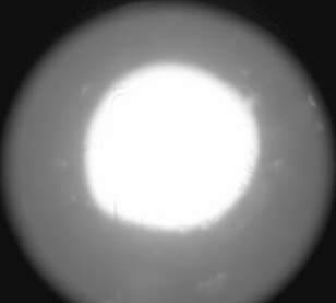 |
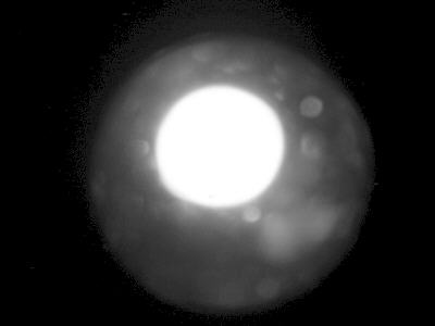
| The above image was taken with a
digicam hand held a little further away from the eyepiece
than normal to give an idea of what to expect when the field
iris is fully open with a x 10 objective. The
intensity of the 'halo' will vary from one 'scope to
another. It should however diminish significantly when
the field iris is restricted to just within the field of
view boundary. In Darkfield particularly there will be no
discernable halo at all simply because the light
scattered from the specimen into the objective is a tiny
fraction of that which is utilised in normal BF. That is
one reason why DF is so good for delicate renderings and
high resolution imagery. This off axis light exists right across the field of view. |
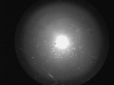 |
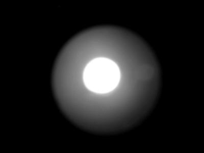
| The same as above but the field iris is almost closed down completely just to show in this particular case how much off axis light still manages to find its way through and up alongside the aerial rays and manifest itself within the image. Some of this errant light is caused by the flaws of the Abbe condenser the degree of which will vary in different stands. Diatoms can be seen lit up in DF: the errant light itself ! |
 |
| Here's a nice example of how a dirty eyepiece can scatter imaging light so effectively. |
 |
| This image shows a problem with an interior optical surface in a binocular head. Notice the restricted fogginess which is shown by off axial camera shot. The problem is a very fine aluminium oxide dust deposit affecting the one eyepiece in a Wild M20 binocular head which can be seen more clearly when the eyepiece is removed. This problem is easily identified by bringing the eyes a few centimetres further back and comparing both exit pupils of the eyepieces. Any significant fogging on one side can be spotted immediately. The only remedy is stripping down the binohead and cleaning. |
Concluding comments
It seems that the average Kohler/Critical illumination system as installed in many stands is not capable of concentrating a perfectly formed image of the source onto the specimen for a variety of reasons. The 'problem' varies widely between stands, but whether this is a significantly image degrading flaw in the compound microscope is a debatable issue, particularly regarding contrast dilution and the effects on resolution in brightfield, and one I take up in Part 2 with a rather surprising revelation.
| All comments welcome by the author Paul James |
Microscopy
UK Front Page
Micscape
Magazine
Article
Library
Please report any Web problems or offer general comments to the Micscape Editor.
Micscape is the on-line monthly magazine of the Microscopy
UK web
site at Microscopy-UK