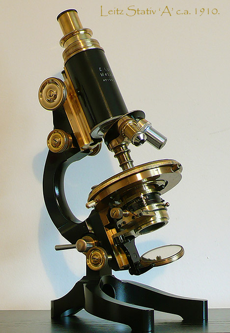
Ernst Leitz Stativ 'A' Monocular Microscope.
Notes on the refurbishing of a fine design ca.1910.
By Ian Walker. U.K.
Fig 1.
Introduction.
I saw this microscope advertised on eBay 'as is' i.e. no box or accessories and being sold by a lady with no knowledge of microscopes, selling off some items from her grandfather's possessions. So it was a gamble whether it was going to be in working order optically and mechanically although she described it as best she could.
What attracted me to the stand were its elegant lines and the fact it was second only to the Stativ 'AA' in the Leitz hierarchy of stands whilst having a good quality condenser and versatile sub-stage mechanics. The main difference between the 'AA' and 'A' were the objective line-up supplied and complexity of the stage, the 'AA' having a mechanical stage built into the design [see Fig 2.] whilst the 'A' has a removable one or simple stage clips like this one. Indeed several versions of these stands were supplied by Leitz in their catalogues differing considerably in the price and supplied optics plus stage complexity.
The notes I make on re-furbishment of the microscope are guidelines only and from my experiences working on numerous stands of different vintages, everyone has their own methods and materials for working on old microscopes.
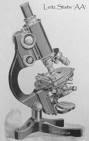
Fig 2.
Ernst Leitz, their best stand of the time the Stativ 'AA' in this photograph ca. 1902, I don't know when it was first introduced but probably around this date, it still appears in the 1913 catalogue. By the 1923 catalogue it had gone from the line-up of their stands.
Other microscope stands.
I have always the liked bigger 19th & 20th century stands finding the smaller ones harder to place and more 'fiddly' in use being only 11 to 12" tall in some cases but this stand is 14 1/2" tall at a tube length set to 160mm and a normal operating angle. The price was modest (a two figure sum) so I bought it.
In the past for re-furbishing and learning projects I have owned the classic Zeiss 'Jug-Handle' design from the early 1900's together with later designs from Zeiss like the black and chrome Stand 'FZ' of the 1930's and an early Leitz binocular stand the 'BIN' [see Fig 3.] together with Watson Edinburgh and Swift Challenge 'C' Victorian stands but for various reasons sold them on knowing they were in much better order after some careful restoration. However, this stand had a certain something about it which I also liked.. it could be that it has had a very hard life since many of the brass parts are well worn of lacquer together with the stage from continual use and whilst working on it, it reminded me off those folk who love restoring old steam engines as the brass has that hard wear and smoothness that comes from years of toil!
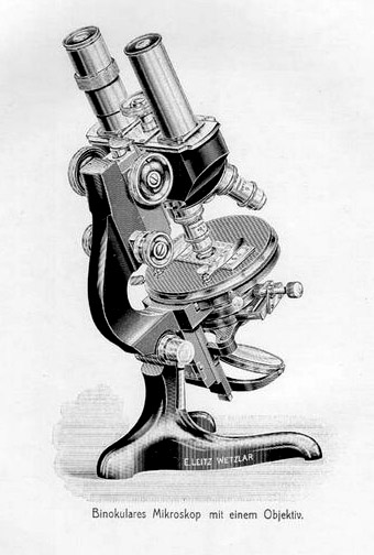
Fig 3.
The design for this binocular stand remained in production for a long period being in the 1913 catalogue and also seen in my later 1923 catalogue. This was a smaller stand but elegant none the less. I didn't like the binocular head the alignment of the tubes was critical for strain free viewing and the image duller than that of a good monocular design, the typical 'light amber' cast of an old binocular design could be seen looking down the eyepiece tubes with eyepieces removed. This one was typically fitted with an Abbe condenser.
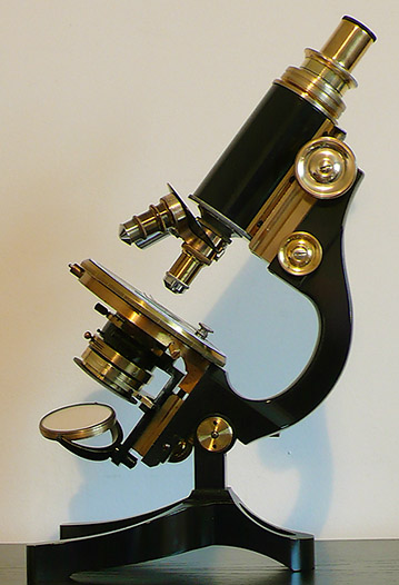
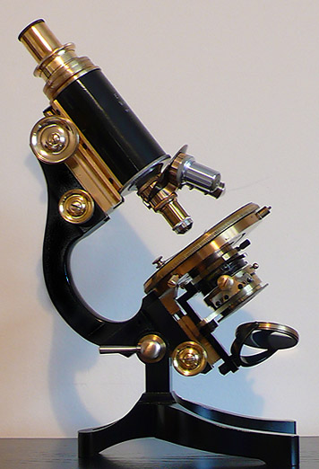
Fig 4.
Two views of the Leitz Stativ 'A', a complex sub-stage is provided whilst quick release for the limb is very useful. A draw tube running in a fine grade friction fit red felt liner offers a good range of optical tube lengths with a marker at 160mm which can be seen above. The nosepiece after dismantling, cleaning and re-fitting has an excellent damped rotation with very positive click stops for the three objective placements whilst care has to taken not to over tighten the central fixing screw since this acts on a cone which sets the friction level and if it were to be screwed too tight the turret will not turn with ease and may be difficult to release.
One anomaly and it was the same as the Leitz 'BIN' stand I had is the R.M.S. thread seems very selective in what can be fitted, my Watson objectives of the period cannot be screwed in neither can some of the 1970's LOMO objectives but it will happily take Leitz, B&L and Spencer objectives; there appears to be no distortion or damage to the R.M.S. receptacles for the objectives and they are of very solid brass construction.
First impressions not so good!
I was pleased to see the microscope well packed in tightly rolled up newspaper 'balls' and although no box shown in the sale it was supplied in a wooden microscope box but with so much packing tape on the outside it was difficult to decide whether original or not but no fittings inside as such. From the outset it looked if I had my work cut-out with a list of things needing attention:
1. Centring disk missing from stage, a new one would be nice to have.
2. One stage centring screw missing the other too badly damaged to restore to working condition, better was the fact that the shafts were not broken off in the stage centring holes.. some new ones would have to be made, see later.
3. Course focus, one tooth missing from the pinion, at first this seemed to be a disaster but strangely on operation hardly noticeable, the broken tooth had been well ground out of the pinion, better in some respects than a damaged tooth constantly grinding against the rack.. this looked to have been done many years ago.
The trick here after re-furbishment with a missing tooth is to find the 'sweet spot' as every full turn of the course focus there will be a 'loose' spot where the tooth is missing this position should be avoided at the normal focus point for your objectives and can be found by experimentation of rotating the pinion one tooth at a time as the tube assembly is offered up to the pinion several times each time focusing up on a slide to find any slack [including slightly above and below the focus point] which would be annoying.. once a good compromise is found it is best not to remove the tube assembly again.
4. Fine focus not operating although the controls were turning.. albeit stiff and uneven.. best not to go any further with refurbishing until investigated!
5. Supplied objectives were 2 off 10x one by Leitz the other by Bausch & Lomb, the third, a Leitz 100x O.I. NA 1.30 was useless due to the front element missing!
6. Un be-known to me the stand had been re-painted this looks to be of fairly recent origin [as a guess in the last 30 years] but it had thankfully been done pretty well and integrated quite nicely with the original back lacquer.
It is quite easy to tell on these stands if it is paint or original black lacquer since shining a bright torch close up you can see right through the lacquer to the brass below this appears black with normal light falling on it, paints are opaque, the re-paint job was mostly on the foot and supports.
7. Removable vulcanite stage covering [vulcanite is a form of hardened rubber] worn with plateaus and depressions, would be nice to restore this flat and to a good finish.
8. Small but noticeable chip out of the glass of the top element of the condenser, after tests on completing re-furbishment shows this is visible with condenser focused with the No.3 Leitz 10x objective but not so with higher powers, it appears as an 'irregular shadow' in the field of view but can be minimised by lowering the condenser slightly.
Where to start.
The first thing to look at as stated in No. 4 above was the fine focus mechanism since if this was damaged beyond repair it wasn't worth going on with detailed dismantling and restoring. More often than not the problem is the grease which has seized on the running surfaces and the spring inside the focus mechanism is not strong enough to act on the downward motion of the fine focus control so the focus remains pretty well static irrespective of turning the control.
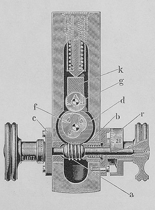
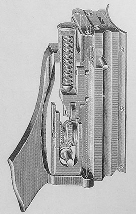
Fig 5.
Fig 5. shows the fine focus mechanism introduced in 1902 and remaining virtually un-changed and still appearing in stands in the 1923 catalogue. In my opinion it is a good design being quite simple. A cam 'f' rotates endlessly driven by a worm drive in line with the fine focus control. As it rotates it pushes against the circular rotating metal wheel 'g' which in turn acts on the fine focus slider. A spring under compression acts downwards to push the fine focus slider down as the focus is lowered, the motion of fine focus reverses if you go past the highest normal operating point shown as minimum-maximum travel lines printed on the tube assembly but no problem just keep turning and you will return to normal operation!
What I was surprised to find on dismantling was the toothed cog shown better in Fig 5. right but labelled 'd' in the left diagram is made of vulcanite [it looks like hard black plastic] I am not certain why Leitz decided to use this rather than mild steel or brass alloy but it is bound to wear over the years, fortunately mine is in good condition but with some wear causing a small degree of back-lash in the fine focus. Having seen all the parts were undamaged the assembly was dismantled and thoroughly cleaned using white spirit or alcohol as appropriate, the mechanism can be seen after the tube assembly is removed from the microscope by removing two small screws 'B' in Fig 7. below and pulling off the tube, the small plate will be under tension from the spring so make sure the spring doesn't ping out as the plate is withdrawn.
Below are some notes on the fine focus mechanism, the old saying ''if it ain't broke don't fix it'' comes in here so if your sample is working smoothly, consistently with little or no backlash it should be left well alone....
In terms of removing the parts of the fine focus inner mechanism from the stand for cleaning.. the two screws on one side only of the limb ['D' Fig 6.] need to be removed the problem here is first removing the associated fine focus knob held in by a centrally placed brass screw ['C' Fig 6.] the slot of which tend to be very thin and easily damaged as these had been over the years. Using the wrong screwdriver is bound to cause problems, I have made a special blade for this type of work from an existing screwdriver grinding it very thin but this of course weakens it so good contact with the screw head is essential.
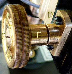
Fig 6.
The next problem are the knobs ['E' Fig 6.] fit on an almost imperceptable cone shape this being 'turned' on the steel shaft in production this is to allow the correct distance of the knob from the limb and tight fit of the fixing screw preventing the knob turning accidentally. Holding on to the other fine focus knob and turning the tone you want to remove side to side usually works but in some cases it won't budge and you will have to clean the mechanism in situ. It is best if the shaft is removed if possible since what can greet you is a mechanism covered in deposits of old oil or grease usually mixed up to a 'black sludge'. The shaft with worm drive is coaxed out of the stand by first removing the remaining focus knob and by slowly turning and very gently pulling the shaft and hence the worm drive out of the limb leaving the cam 'f' attached to cog 'd' which can be pulled off by hand.
Cotton buds on sticks are really useful here soaked in pure alchohol to clean out the bearings and gunge behind the mechanism whilst the vulcanite cog can be immersed in a small pot of cleaning solution [I used alchohol but not for long not knowing the effects on the old vulcanite] and brushed clean etc. There is a spring to reduce back-lash of the mechanism which fits over the shaft on one side, [seen in section to the right of the worm drive in Fig 5. left drawing] make sure it is free to move and not jammed on the shaft this can be very dirty too.
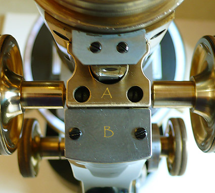
Fig 7.
The two screws 'A' in the above photograph are to set the friction of the course focus controls they should be tight enough for the spindle not to wobble but not tight enough to cause drag as the controls are turned.
The two screws 'B' hold the fine focus spring under tension this acting on the underside of the small steel plate shown. Removing the screws, plate and spring the tube assembly can be withdrawn from the stand. Normally with good lubrication this will feel easy and very smooth with no stiff points to hinder the action but chances are with a 100 year old stand it will be difficult to withdraw and some force may be needed applied gradually under the tube to remove it from the stand. The fine focus mechanism and controls remain with the stand whilst the tube and course focus controls come away as an assembly revealing the fine focus sliding brass surfaces and mechanism shown in Fig 5. The sliding surfaces must be thoroughly cleaned of all original lubricant and built up deposits for a smooth and concise action and new lubricant applied in modest amount.
Getting the new lubrication correct is tricky since too thin and the weight of the tube will cause 'jerks' in the motion and too thick and the spring has insufficient power to overcome the grease I found a light to medium viscosity Nye grease correct after experimentation and before final assembly of the focus parts the sliding action can be checked by hand to see if it is free running, any stiff points and you will get problems as you focus up and down. No lubricant is applied other than the brass surfaces neither the worm drive or vulcanite cog, only to the sliding surfaces and shaft at each end as it rotates through the limb bearings.
After dismantling of all parts, thorough clean and re-greasing the fine focus works well albeit with some inevitable [slight] back-lash due to wear in the vulcanite however this is acceptable and the motion very smooth, damped and consistent.
Moving on.
Now I was satisfied the fine focus was working it was a matter to give the scope paintwork and tube assembly a good clean to see how well it is going to look after a final polish up after re-greasing. Using a well dampened but not wet cloth previously moistened in a weak solution of soapy water I go about cleaning the surfaces avoiding greased areas which would spread when wiped. I usually repeat this process several times without rubbing hard, each time a little more dirt is lifted. I am always amazed how a dull, dusty and lack lustre stand nearly always looks so much better after a clean. The stand is then 'buffed' using a soft cloth that previously has been used for polishing wood so there are a little remain of polish embedded in the cloth, no direct spray is used, this again is done several times until the paint and lacquer get a good shine.
The stage.
It is not often I get beaten but the locking ring similar to those used on LOMO stands to hold the rotating parts together on the stage was so seized I couldn't shift it. I always like to clean the sliding surfaces and re-oil, even with my tool made specifically for this purpose it wouldn't shift so I had to be satisfied with using existing lubricant cleaned out as best as I could in situ and add a little new medium viscosity oil. Fortunately the rotating action wasn't bad to start, many of these are solid and won't budge but this was reasonably free and damped action. I never use grease on stage rotating parts this gives a very stiff action but with a good Nye medium viscosity oil a wonderful fluid action can be obtained as in this case.
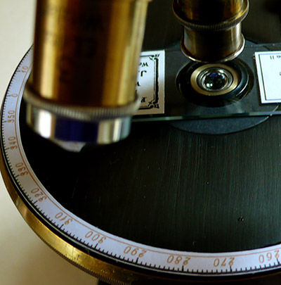
Fig 8.
In the photograph above you can see the new centring insert made from twin laminated card and cut using a circular cutter, the light makes it appear lighter than it is but is actually dark gray and augments the stage finish. The vulcanite surface has been finished off with a fine grade wet emery paper held in a wooden block where it is drawn over the surface in long even strokes to give a consistent finish, a technique I have used after respraying later painted stages. Again the light picks out irregularities, in reality it appears smooth as shown in Fig 9. with just a hint of the fine lines visible here. After the emery cloth is used the vulcanite disk is washed with soapy water and then finished off with spray polish to bring back a dark consistent lustre. Also seen part of the new paper graduation ring calibrated in degrees easily removed if required, this was designed in TurboCad CAD package and the font and colour selected to compliment the age and brass used in the stand.
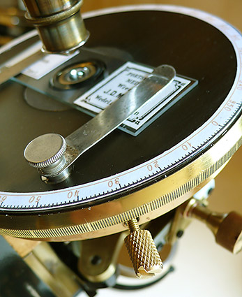
Fig 9.
Detail of stage surface and perimeter graduations.
A more life-like view of the finished stage surface and insert together with a view of the new centring screw shown in more detail in Fig 10. The markings filed around the brass perimeter were made previously in the microscope's life, these were augmented by markings in pen which have been removed
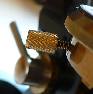
Fig 10.
A brass computer screw head cut and bonded to the filed down head of a brass screw to form a new centring screw for the stage.
Two new stage centring screws were needed, I found some brass screws about 1" long with round heads in my hardware supplies [probably metric thread but don't know] filed the heads flat to around 0.25mm thick and bonded them to some old brass knurled desktop computer mounting screws [these are or were typically found at the back of the computer holding power supplies and fans in place or holding the mother board in place]. The threaded portion is removed by hacksaw, finished with a file and then emery cloth for a flat mating surface. The end of the assembled screw assembly should be filed to a smooth rounded end so as it turns against the hardened insert in the lower part of the stage neither the screw nor stage jump or jitter erratically as the screw is turned and stage centred. The finished article although not authentic is functional and using materials akin to the rest of the stand.
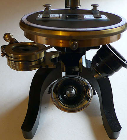
Fig 11.
Showing the sub-stage assembly.
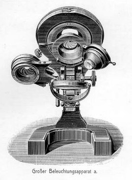
Fig 12.
From the 1913 catalogue showing the Leitz diagram for the same sub-stage fitted to a different stand and clearly visible the upper diaphragm operated by long lever rather than the standard condenser diaphragm which is adjusted by a much smaller short-armed spherical control, the condenser diaphragm being swung-out to the left.
Fig 11. shows the sub-stage, the condenser housing was well worn so a new coat of black paint was applied by fine brush. After drying, the edges were burnished to the brass to give an authentic look of use. The condenser itself is discussed in the 1913 catalogue but the on-line one is in German which I cannot translate. There are at least 3 elements and perhaps more but it could be an even more sophisticated achromatic or aplanatic-achromatic since the shape is correct [see Fig 13. below], this is completely different in design to the Leitz Abbe N.A. 1.2 and N.A. 1.4 condensers of the same period. Suffice is to say it is an excellent condenser, well corrected, with close working distance and easily has sufficient aperture for a 40x N.A. 0.95 objective.
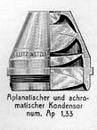
Fig 13.
Detail from the 1913 catalogue of the aplanatic-achromatic condenser N.A. 1.33, the shape and style is very similar to this stand, the top element can be removed but unsure whether this was just for manufacture or could be used as a low power condenser in this state.
The housing of the condenser is of unusual design since there is a diaphragm just above the optical top element. This one is operated by the long lever shown in Fig 12. had damaged leaves two of which were removed. The leaves are specially curved and shaped to fit the inside cupped surface of the condenser housing so nothing could be done except remove excess oil and damaged leaves and re-assemble with the seven remaining leaves in situ which still work OK at medium to small aperture but opened to maximum and left. You can see that the optics of the condenser in Fig 12. can be swung out of position leaving the upper diaphragm but what use this had I don't know since low power work the concave side of the mirror could be used. The oblique illumination assembly can also be swung out of position and clicks 'home' on a sprung catch. The assembly has been removed from the stand, all parts dismantled, cleaned and re-lubricated for smooth and tactile operation.
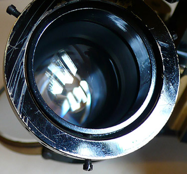
Fig 14.
Tests after re-furbishment of the microscope showed that there seemed to be a problem with the condenser out of alignment although fine adjustment of centring can be obtained by three tiny screws two of which can easily be seen in Fig 14. above, they have limited travel. After some investigation at some point the sub-stage mounting bracket had been screwed back onto the stand about 1 mm to one side not allowing sufficient adjustment of the tiny screws. There were no pins to ensure correct re-assembly of the mounting bracket often seen in various parts of LOMO scopes. As shown the three screws have been adjusted for correct centring any further travel would cause the condenser to not swing back in and out of the outer casing which includes the upper diaphragm.
Accessories.
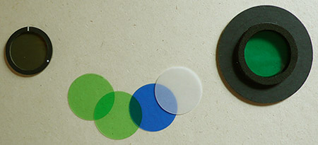
The stand does not include a swing-out filter tray which is a shame so I made my own push-in filter holder that includes standard green and blue acetates made with a circular [compass] cutter. The circular card disk is oversized compared to the brass work of the sub-stage so can be rotated to a certain extent.. useful for the polarizer for alignment. It is made from laminated card with a foam ring made from SLR camera kit repairs the inner of which is cut to a convenient size for the circular filters to sit snugly into place on a small 'step' but easily pushed out.
 .
.
Fig 15.
Polarizer on the left, the filters and push-in filter holder all easily made.
Conclusion.
I am happy with the outcome of this microscope, after a lot of intensive work it has gone from a rather sad and un-used display [?] model barely working to fully operational capable of excellent results. Although it has had a hard life seen by the extensive wear and previous work done on it over the years it still can still look both aesthetically pleasing as shown in Fig 1. together with smooth running controls still working pretty well after nearly 100 years. Together with suitable optics of which I use an old water immersion Spencer 3mm achromat N.A. 1.10 it is a good stand for diatom 'dotting' due to the condenser of wide aperture being well corrected along with versatile oblique illumination. It is easily converted into a simple polarizing stand by the addition of a polarizer-analyzer and with the graduations added to the stage simple petrographic study can be achieved.
One point is worth noting though is the stand is unstable with tube horizontal and with the tube in its normal operating position not as steady laterally as say the tripod design of the smaller, lighter Watson Edinburgh.
Comments to the author Ian Walker are welcomed.
Useful link:
Gordon Couger's 'Science Info' site has many old Leitz, Zeiss and other microscope makers catalogues in PDF format together with links to sites and other useful microscopy information.
Microscopy UK Front Page
Micscape Magazine
Article
Library
Published in the April 2008 edition of Micscape.
Please report any Web problems or offer general comments to the Micscape Editor .
Micscape is the on-line monthly magazine of the Microscopy UK web site at Microscopy-UK
©
Onview.net Ltd, Microscopy-UK, and all contributors 1995
onwards. All rights reserved.
Main site is at
www.microscopy-uk.org.uk
with
full mirror at
www.microscopy-uk.net
.