
High power light emitting diodes that emit a fairly good approximation to daylight have been available for some time now. There are several models of them available at this point in time. One model that is particularly useful for microscope application is the K2 model. At one time these were difficult to obtain, but now they are readily available. The white 130 lumen 1500 mA model is particularly useful. (There is a newer 200 lumen model of the K2, but it is difficult to obtain at this point.)
There is a more recent model called the "Rebel". These are very small and very bright. There is now available a "star" mounted tri-emitter version of these that puts out an incredible 540 lumens at 700 mA. (The small size of the emitter and the fact that there are three light sources on each unit may make these less suitable for some applications.)
Tungsten filament lamps, even quartz halogen ones, emit a very large fraction of their radiation in the infrared, and the red ends of their visible spectra are much stronger relative to the blue ends relative to daylight, giving light from them a very strong orange cast. Blue filters can be used to produce an approximation of daylight, but obviously they dramatically reduce light intensity.
White light emitting diodes emit most of their energy in the visible spectrum, they are quite efficient, and their spectra are a reasonable approximation to daylight.
Stereo microscopes manufactured in recent times have commonly utilised fibre optic illuminators using quartz halogen bulbs. These are almost never filtered, so the views through stereo microscopes equipped with them always has a very strong orange cast.
It seemed sensible to design and fabricate a light emitting diode illuminator for these systems. My solution to this problem is presented here.
After making some tests by placing an illuminated K2 LED in front of the input of a fibre optic ring light, it was apparent to me that K2 LEDs were bright enough to use for this purpose. These tests also indicated that the design required that the LED be a few millimetres from the end of the fibre optic cable.
I obtained a piece of 57mm square aluminium bar stock and placed it in a band saw. I cut off two pieces, one 43mm thick, and the other 15mm. Before making the cuts, I drew a line on one side so that if the bar stock were not perfectly square, I could match the cut faces properly. (This probably would not have been necessary.)
I made sure that the cut edges were reasonably flat and then drilled a 16mm hole all the way through the square face of the 43mm piece. I then took a boring tool and bored out the face that would butt against the 15mm piece in the final illuminator to 32mm for a distance of 10mm.
The next step was to bore four 5mm holes 8mm from each face near each corner in the 15mm piece of aluminium all the way through. Then I drilled 4.5 mm holes in the 43mm piece on the bored side and tapped them to receive 5mm screws. It is very critical that the holes from the two pieces match perfectly or it will be impossible to assemble the device!!!!
The next step was to drill a hole on one of the faces of the large piece all the way into the 16mm hole at its centre. This hole was drilled part way through with a 6mm bit, than a 4.5mm bit the rest of the way, then the hole was tapped, and a 4mm knurled screw was added to lock the fibre optic cable when the assembly was complete.
It was now time for the final step. I soldered the electrical connections to the K2 LED, and then drilled two 2.5 mm holes in the 15mm thick piece of aluminium to hold the LED. I tapped the holes for 3mm thread and places a short piece of threaded rod in each. I put heat conducting paste on the back of the LED, and then put a nylon washer over each threaded rod, and finally tightened down a 3mm nut on each threaded rod.
I drilled a hole large enough for the wire, pulled the wire through it, and attached banana plugs to the other end of the wire. I assembled the two pieces of metal with four 5mm screws, and the illuminator was complete.
The images below show the two aluminium blocks with all the holes drilled in them, and with the LED attached. Note the hole on the bottom of the larger aluminium piece. The screw to retain the fibre optic cable fits there. The other end of this threaded hole is visible on the right image inside the large hole in the centre of the piece.
I attached my fibre optic ring light to it and connected a power supply to the other side. These LEDs are capable of handling 1500 mA current, but I feel safer running them around 1000mA when they are powered up for long periods of time.
The two images below show the final illuminator. The image on the right shows the illuminator assembled, and the one on the left shows it with a fibre optic ring light attached.
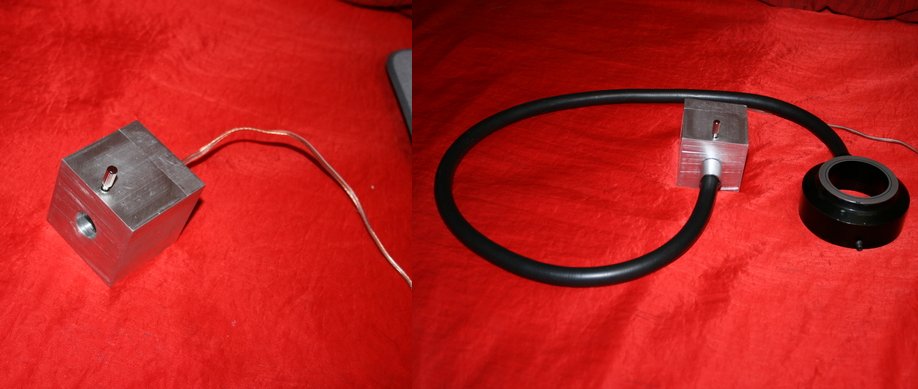
At 1000 mA the illumination is not extremely bright, but it is quite adequate. It is noticeably brighter at 1500mA. The colour quality is excellent, dramatically closer to daylight than a quartz halogen illuminator. Of course, unlike the quartz halogen tungsten filament bulbs the colour quality does not change with current. This is a dramatic advantage!
The new Luxeon Rebel Star-white tri-emitter model with its 540 lumens would almost certainly be as bright as the original quartz bulb and it would not be orange. Although the fact that there are three sources on each of these units would introduce severe problems if one were to try to adapt them to a standard compound microscope illuminator, that fact certainly would not matter here.
The Rebel Star tri-emitter costs about five times as much as the K2 1500 mA white LED. However, it still costs a small fraction of what the commercial quartz halogen LED light sources cost, making it a far more economical solution than purchasing a quartz halogen system.
There are occasionally research projects that require illumination using coloured light. The non-white light emitting diodes have a rather narrow spectral distribution. This means, of course, that they require no filters. It also means that the light in that narrow wavelength distribution is dramatically brighter than quartz halogen tungsten lamps!
The eyes of many organisms (such as insects) are insensitive to red, so by using red LED illumination, one can observe nocturnal behaviour in such organisms. Many insects are bi-chromatic, that is they have only two types of colour pigment receptors. There are tri-chromatic insects like bees and many butterflies. However these insects have their third colour pigment receptor in the ultraviolet rather than red. The red K2 LEDs emit their light around 625nm, just below the visible range for insects, but well within the spectral range of human eyes.
All comments to the author Robert Pavlis are welcomed.
Microscopy UK Front Page
Micscape Magazine
Article Library
Please report any Web problems or offer general comments to the Micscape Editor .
Micscape is the on-line monthly magazine of the Microscopy UK website at Microscopy-UK