 |
| Aligning The Zeiss Photomic's
"Headrig" By Paul James |
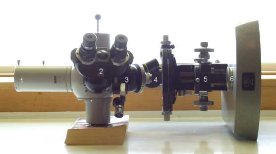
Anyone who has had experience of using one of the Zeiss Photomicroscopes versions I, II, or III will have soon realised that the stand is a complex one. Such an internally sophisicated optical device that was designed, manufactured then assembled with a high degree of precision is no mean feat of optical and mechanical engineering. However, the fact is that after 40 or 50 years of use and in various ownerships, wear and tear PLUS the inevitable twiddling that some stands might have incurred, would have undone Zeiss's original collimating sequences on the assembly lines. Having acquired a Photomic II headrig a while back with the view of upgrading my Photomic I's stand to support simultaneous observation/photographic facility I soon found that both the headrig and original stand required some optical adjustments to maximise their designed potential. I should imagine the fundamental adjustments to the type II headrig are very similar on the I & III . It appears that all 3 stands as well as the "Universal" share a very similar design scheme and so the following sequencing and adjustments may therefore apply too.
I have not attempted to extend the alignment process into the internal 35mm film cassette simply because I no longer use that facility: I suspect that few do these days.
| NB.......To simplify matters I have written this account from the perspective that the microscope in question is obviously out of alignment, and that the owner will decide to start from scratch. This avoids the writing of a more complex sequence of procedures. I therefore advise anyone who feels comfortable with the prospect of having to strip parts off and re-build to facilitate alignment in stages etc., to read through the following notes entirely before starting. However, I cannot assume any responsibility for mishaps or damage caused by accident or otherwise from your efforts to collimate your own stand. |
First things First
I repeat.... it is essential that the whole sequence I describe below is read through before attempting any alignment work. Familiarising yourself with the sequences of procedure is in my humble opinion half the battle, and reduces the chances of making mistakes or false assumptions. There are 'traps' for the unwary along the way which are easily fallen into, but as long as you make notes, and also use a felt tipped pen to mark some exterior adjacent parts so that they go back exactly as originally found, then little can go wrong. It is more than likely that you will be repeating some of the procedures as you get nearer to true alignment, because one adjustment often affects another, so it is necessary to whittle down the errors sequencially.................. It's rather like lining up a series of coins on your table into a straight line by viewing from one end and tapping the each coin in sequence until eventually they appear in a straight line.
My own method of adjusting the 'scope stemmed from the fact that some of the optical parts or modules that make up the 'scope are not adjustable. Therefore logic demands that we have to take this into account whilst planning any series of adjustments.
The NON Adjustable modules are :-
a) The lamphouse and its iris. (Centering lamps only affect the eveness of illumination within the source's field)
b) The Optovar (3) is fixed inside the objective turret housing module (4) , though the housing as a whole is adjustable*.
The Adjustable modules are ;-
c) The prism slider assembly above the objective turret has the capacity for tweaking in one plane only.
d) Both the trino/photo tube and binocular head units (1&2) have standard 120 degree grubscrew lateral settings.
e)* The Module (3) which supports both the Optovar unit and objective turret allows lateral adjustment using 4 grubscrews around its perimeter.
f) The base unit's field lens/90 degree reflector module (6) can be adjusted.
g) The substage condenser is adjustable of course but having a subordinate though vital role in microscopy, has no bearing on the collimating process.
|
Strategy
All the adjustments can be performed with the stand in its normal vertical position, excepting the initial adjustments made to the base mirror/iris assembly (6). To facilitate the adjustment of this component the stand should be tipped on its side so that the base mirror assembly can be adjusted from the underside of the base whilst allowing convenient access to both viewing ports. A paper back support under the prism housing is ideal for this, reducing flexure to an absolute minimum since the bulk of the top hamper is directly above it. Note that the bino head (2) can be rotated into a more convenient attitude for alignment checks if need be. Once the initial process of aligning the base's field lens/mirror assembly (6) is successfully completed the 'scope can be worked on in the normal vertical stance.
Getting Started
Step 1) Without doubt the most important prerequisite before tweaking any part of the headrig is to see to it that the light from the source is very accurately aligned through it. Strictly speaking it is desirable to view the source from the farthest end of the 'scope, without any intermediate optics in place which if present and a little askew will prejudice the view of the source and cause misalignment from the start. The prism slider module can be left undisturbed for the moment.
You'll need to remove the following : both substage condenser (5) and Optovar/turret housing (3).
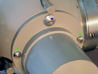
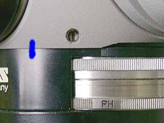 |
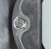
The Optovar/turret module is held in place by 4 grubscrews. One of which is shown above. They may have locking screwcaps which are much shorter so these should be removed first. With the 'scope positioned in the vertical, mark the interfacing of the headrig and module with felt tipped pen to record their original mating position. Now hold the module firmly before undoing JUST 2 ADJACENT grubscrews sufficiently to allow the module to come away freely. By leaving the other 2 grubscrews undisturbed will guarantee the module's intial registration when reassembled, which should reduce time spent if it is required to adjust it later. Take great care when lowering this Optovar/turret module because it is heavy enough to slip from the fingers. You might like to slide off the turret dovetailed to it before removing the upper Optovar unit to reduce chances of mishap.
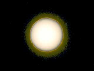
First make sure the photoport is mechanically centered on the headrig, ie its base appears uniform and concentric in relation to its counterpart on the headrig. Now using a phase telescope in the photoport, with the prism slider set to simultaneous viewing with binohead, scrutinise the field housing on the base unit (6) using an external lamp to brighten up its surface. If it appears a little off axis true up the photoport by adjusting it at its base on the headrig. Now adjust both the lamphouse iris to minimum, and adjust the base iris (6) so it is slightly wider than the source. Make sure your phase telescope is focussed on the upper iris leaves of the base unit. The illumination can be adjusted accordingly. What now should be witnessed is the state of the alignment between the source and the base iris's halo......quite likely appearing askew :-
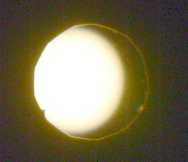 |
This image has been amplified for illustration purposes, your 'live' view through the phase telescope will be smaller, but still easily interpreted.
Step2) The next task is to bring about concentricity of the source and base iris by adjusting the field iris's mirror cell from underneath the base. The 'scope will have to be tipped on its side as mentioned earlier. For simple convenience you can use the phase telescope in the binohead swung around to near vertical to view your initial efforts at aligning the light output. When effectively centered or nearly so, compare with the photoport's view with the phase telescope. Unless you find both identical, trust only the photoport's view for final tweaking.
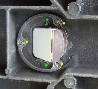 |
The underside view of the base iris assembly is shown above. I think most Photomic models are similar in principal. Note the 'horse shoe' clamp and its 3 screws. The 2 mirror cell clamping screws should be left alone. Getting the base's prism/mirror assembly to accurately guide the source's light up through the dead centre of the headrig is an operation that cannot be fudged and later annulled by adjusting the headrig's components. It has to be as accurate as you can possibly make it. Fortunately this is not too difficult to accomplish, though a trifle fiddly.
 |
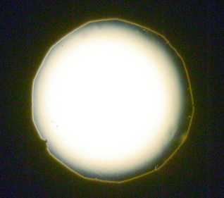
Before starting it should be understood that the mechanism for tweaking the horse shoe support relies on a 3 point system. Each of the 3 screws, one of which is shown above, is spring loaded, and importantly tightens against a threaded sleeve which has slots visible around the screw head. By loosening each screw a little at first the sleeves can be rotated either way to effect the lowering or raising of the horse shoe support at that point. Use a fine watchmakers screw driver to rotate the sleeve. By observation through the phase telescope you can see the effects of altering one or more of these sleeves. The springs allow the effects of adjustments to by noticed without need of tightening each every time etc.. When satisfied that the view looks similar to that show below, you can 'nip' up each screw carefully....... the threads are prone to strip in the aluminium alloy base. Be prepared to repeat the procedure as alignment shifts a little when nipping up the screws. Patience is a virtue indeed but finally, alignment should appear as shown below.
 |
| At last ! |
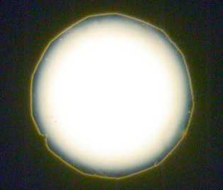
Step 2 We now have an accurately tweaked beam of light ascending through the centre of the head rig's optical assembly. The 'scope can now be tipped back to vertical. Next step is to replace the Optovar/turret module (3) back into its original setting. Accomplish this accurately using the tell tale felt tipped pen marks with both grubscrews back and nipped up. Now the accuracy of the original setting of the Optovar/turret module can be checked. Set the Optovar on PH and observe through an ordinary eyepiece back in the photoport through an empty objective port on the turret, focussing accurately on the leaves of the base iris assembly (3). There you will see a familiar view, albeit much enlarged, of the source's circle of light within ( hopefully) the base iris halo :-
 |
This is a typical view after mounting the Optovar/turret module.....ie slightly askew. This is of course a view directly through the photoport and the Optovar, the latter is obviously slightly off line. The next step is to bring the Optovar's axis into alignment, so the concentricity of the source/base iris appears true again. By doing this we are also bringing the objective turret also into alignment as Zeiss have obviously aligned accurately both Optovar and turret in the one module.
But before commencing, check again the binohead 's view with that of the photoport, and if necessary loosening the main clamp screw at the base of the binohead and adjusting the 2 grubscrews opposite. Defocussing the Optovar so as to expand the source's circle of light facilitates the centering against the eyepiece field boundary. The binohead's alignment can now be trusted when tweaking Optovar/turret module.....and is of course far more convenient to use for this next operation.
Adjusting the Optovar/turret Module (3)
Now the fun and frustration really begins. You will soon find that getting the source's light pool into the base's iris centre by adjusting these 4 grubscrews is not at all intuitive. As a basic guide, each of the 4 grubscrews which point towards the central optical axis, impart, when screwed in or out, a motion of the source which is exactly at right angles to the axis of the grubscrew adjusted. Best to loosen slightly only 2 adjacent screws at a time and then nip up their counterparts opposite to see for yourself the effects on the position of the source/iris combo. The trick whilst supporting the slightly loosened module is to maintain firm interface contact with the headrig as well as lining up the pen mark(s) with one hand, whilst nipping up/loosening any of the grubscrews with other. Importantly don't forget that if you want to screw in one grubscrew by one turn, then its opposite must be unscrewed one turn etc.. Try to think in logical sequences as you work out how to move the source into the centre of the base iris halo. Adjusting by small measures is the key to success, because adjusting 4 grubscrews is much more complex to get right than 3.
 |
| The view you've been working to achieve! |
When you have achieved this, the 'scope is very near to accurate alignment/collimation, possibly subject to just a little more tweaking, but don't expect a result in 5 minutes......it will in all probability take a lot longer.
Remaining Tasks
I have not mentioned the prism slider adjustment till now simply because in all likelihood it will be fairly accurately aligned because the method of adjusting it is hidden. But if you have difficulty marrying the 2 fields of the photoport and binohead, it may be that the prism slider assembly needs a little tweaking too.
 |
To adjust it.....unscrew the large cheese head screw completely . Loosen the 2 Philips screwheads a 1/4 turn or so. You will notice the eccentric adjuster behind the large central screw which when engaged with a screwdriver and turned offers some leeway of prism assembly movement in one plane only. This can be checked through the binohead and photoport. Its effect on the field in the binohead is much more exaggerated than the photoport. I think therefore a small adjustment here which might cure an alignment problem with your binohead, will have little or no material effect on the photoport's alignment with the source. You can alter the photoport's position slightly if necessary to bring into alignment with the views through the binohead later. There is a fair amount of leeway inside the prism housing as the prisms are much larger than they need to be. What matters most is that the Optovar/objective/base iris/source alignment is still accurate, so a little juxtapositioning of both the photoport/binohead to 'fuse' their imagery for photographic convenience is entirely legitimate.
Finalising
At this stage your 'scope is pretty well aligned, but before putting away your screwdrivers etc., replace with x10 objective or equivalent in its turret, and with the substage condenser also back in place and centered, focus on a slide in BF then remove it and examine the source's field boundary, more especially the edge of the lamphouse source's iris. Open the substage condenser iris completely and then focus the substage condenser on the edge of the source's iris carefully, and examine the consistency of colour around its periphery, as you raise or lower the substage condenser very slightly. What you should see is perfect symmetry of effects all around the iris's edge. An even more critical test is to close the stand's base iris down until it constricts the source's output. The dimming and any colour effects should again be symmetrically disposed around the source's edge.
No matter how accurate your efforts have been, the fact is that the substage condenser needs to be re aligned slightly with each objective on the turret. This inherent lack of absolute parcentricity even from the best manufacturers demonstrates that absolute alignment is simply impossible to achieve. All we can do is get the source lined up through the headrig as accurately as we can.
Concluding Comments
It took me a while altogether to sort out and implement these procedures above. But having said that I now have an 'accurately' collimated Zeiss Photomic stand which performs extremely well especially in the more critically illuminated setups which is precisely why I realigned it in the first instance. The final result was easily worth the efforts and admittedly the frustrations that I'd put into the task. But be aware that the process might have to be repeated in part as you progress through the stages. No matter I believe, for the experience is truly beneficial in the long term, instilling confidence in one's knowledge and ability to get the best out of your instrument. The secret I believe in aligning/collimating optics is based upon the three S's..............Symmetry, Symmetry, Symmetry !
| All comments welcome by the author Paul James |
Microscopy UK Front Page
Micscape
Magazine
Article
Library
Please report any Web problems or offer general comments to the Micscape Editor.
Micscape is the on-line monthly
magazine of the Microscopy UK web
site at
Microscopy-UK