Diatoms and Microscopy
a contrasting combination
René van Wezel
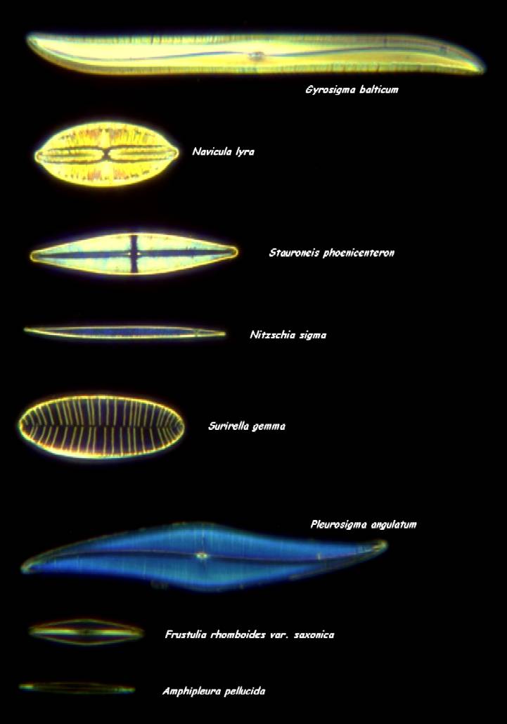
The fine glassy details of diatoms are admired already for hundreds of years, ever since the invention of the microscope. During Victorian times, manipulation of the single valves was considered an art and a pastime, and slides with different species of diatoms were used to thoroughly evaluate the latest microscope objectives for performance.
Figure 1. A typical diatom test slide, produced by Klaus Kemp. The lower two diatoms are being used to evaluate the highest power objectives. Darkfield, 10x objective.
Resolution and contrast in brightfield microscopy
According to Abbe’s diffraction theory, the resolution of a lens is determined by the lens opening (aperture), and the wavelength of the light used. In practicality this means that for a traditional light microscope the limit of resolution is reached at ca. 0.2 μm. In order to be able to reach that level of resolution, the following assumptions are taken for granted: a black and white start situation (in the specimen) and no contrast loss within the optical system (figure 2).
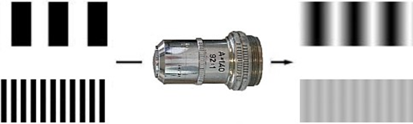
Figure 2. Resulting image from a line pattern, as seen through a microscope objective. Image contrast decreases to zero when line spacing reaches the theoretical limit of resolution.
A diatom valve is glassy and colorless, and forms therefore the classical example of the contrast issues faced by a microscopist. The refraction index of the silicified valve of the diatom is pretty much similar to water and glass, and because of that it is barely visible in the tradional microscopical mountants (figure 2). Therefore, special diatom mountants have been developed which differ in refraction index as much as possible with the specimen. Nevertheless, Abbe’s diffraction limit still holds as an elusive ideal that can only be approached.
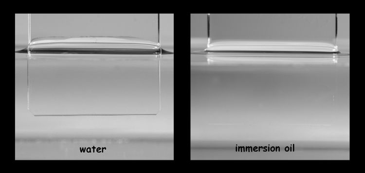
Figure 3. Contrast of a colourless and transparent structure depends on the difference in refractive index with its surrounding medium.
In brightfield microscopy, contrast of a structure is also regulated by the condenser. Ideally, the condenser iris is fully open, with the condenser forming a cone of light similar to that of the objective. Under these conditions, resolution is maximalised (figure 4). Unfortunately, the gain in resolution with a fully open iris is not perceived visually, due to the very low contrast levels. Therefore, the general advice has been to slightly close the condenser iris to around ¾ of the aperture of the objective, which increases contrast considerably without (visual) reduction of image quality.
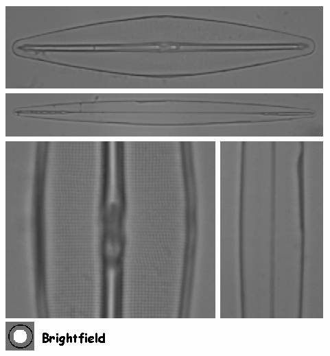
Figure 4. Frustulia rhomboides var. saxonica (top and left) and Amphipleura pellucida (below and right) as seen with an oil immersion objective in brightfield.
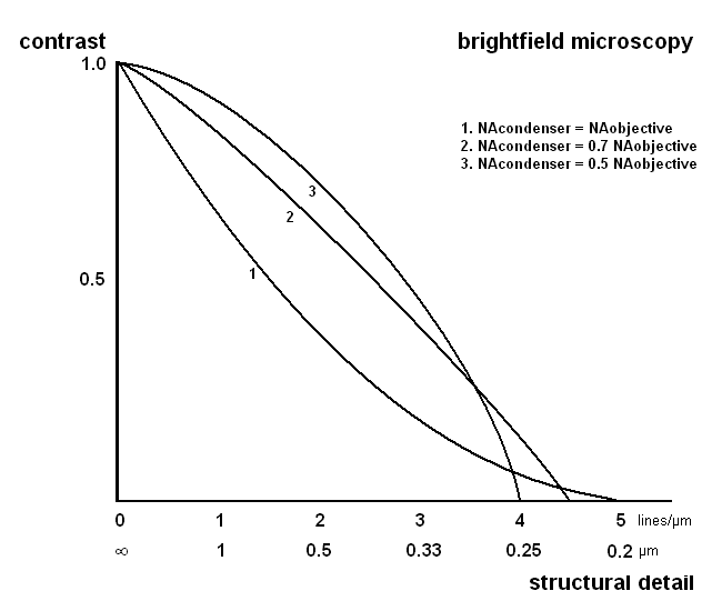
Figure 5. The effect of the condenser aperture on resolution and contrast. Calculated for an objective with an NA of 1.3 and blue light. Adapted from Pluta.
Optical contrast enhancement mechanisms
When light penetrates an optically more dense material like glass, it will get a shift in time compared to light that travels through the surrounding medium. This so-called phase shift has no influence on the wavelength (color) nor on the amplitude (intenstity), therefore it cannot be detected by eye. However, optical tricks have been deviced to change this invisible shift in phase into a visible change in contrast.
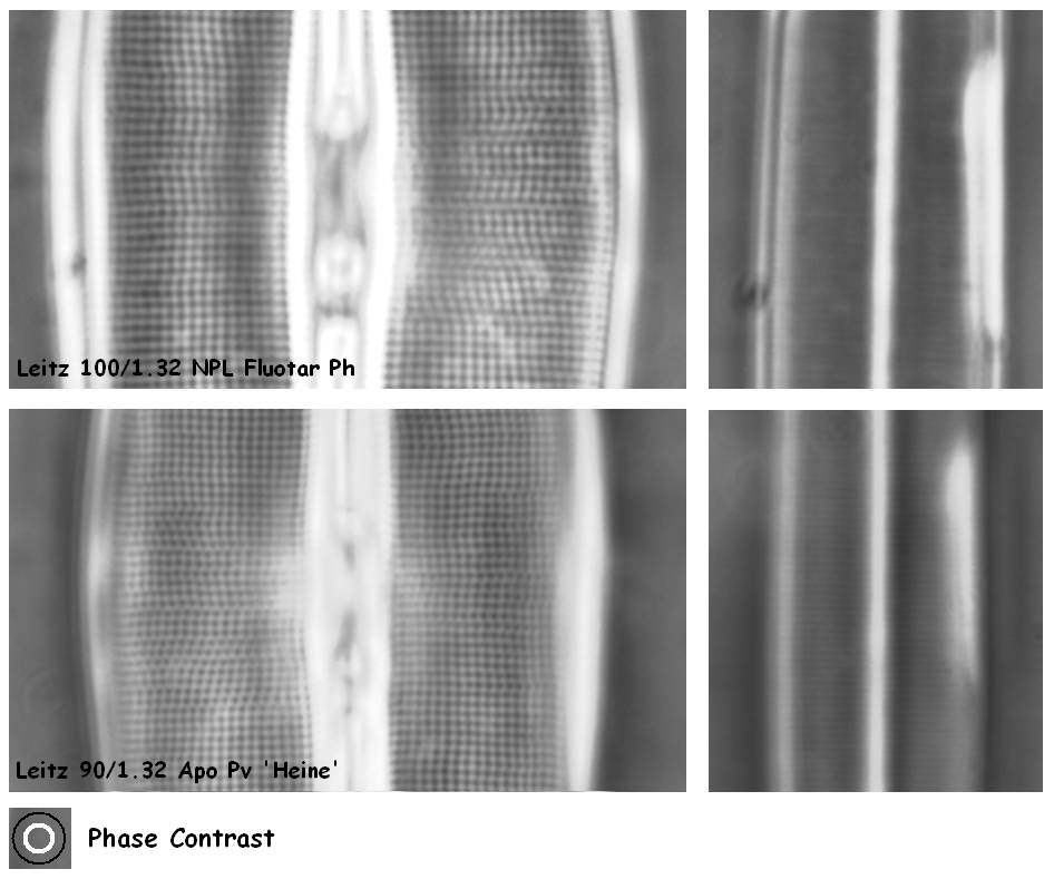
Figure 6.
Most phase contrast sets cannot resolve the striae of Amphipleura
pellucida, but the Leitz Heine system is just about capable of
showing the fine line pattern.
The large condenser annulus of the
Heine system approaches NA 1.0 and needs condenser immersion.
The phase ring in the objectives covers a small part of the objective lens. This results in a slight reduction in performance in brightfield, compared to a brightfield lens without phase ring. Even though this reduction in image quality is visually hardly noticeable, a digital camera will pick up this difference quite easily. Phase contrast objectives can therefore not be regarded suitable for high performance brightfield imaging.
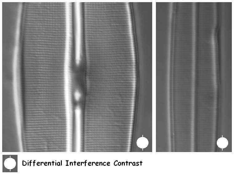
Figure 7. Differential Interference Contrast can resolve the striae of Amphipleura pellucida, provided that the diatom valve is orientated in the right angle towards the shear direction of the DIC system.
DIC systems make use of polarised light which gives a directional ‘shadowing’ effect to the subject. This means that diatoms have to be positioned at a certain angle to the direction of polarisation in order to give highest contrast. Therefore, a DIC microscope should ideally be fitted with a centrable rotating stage.
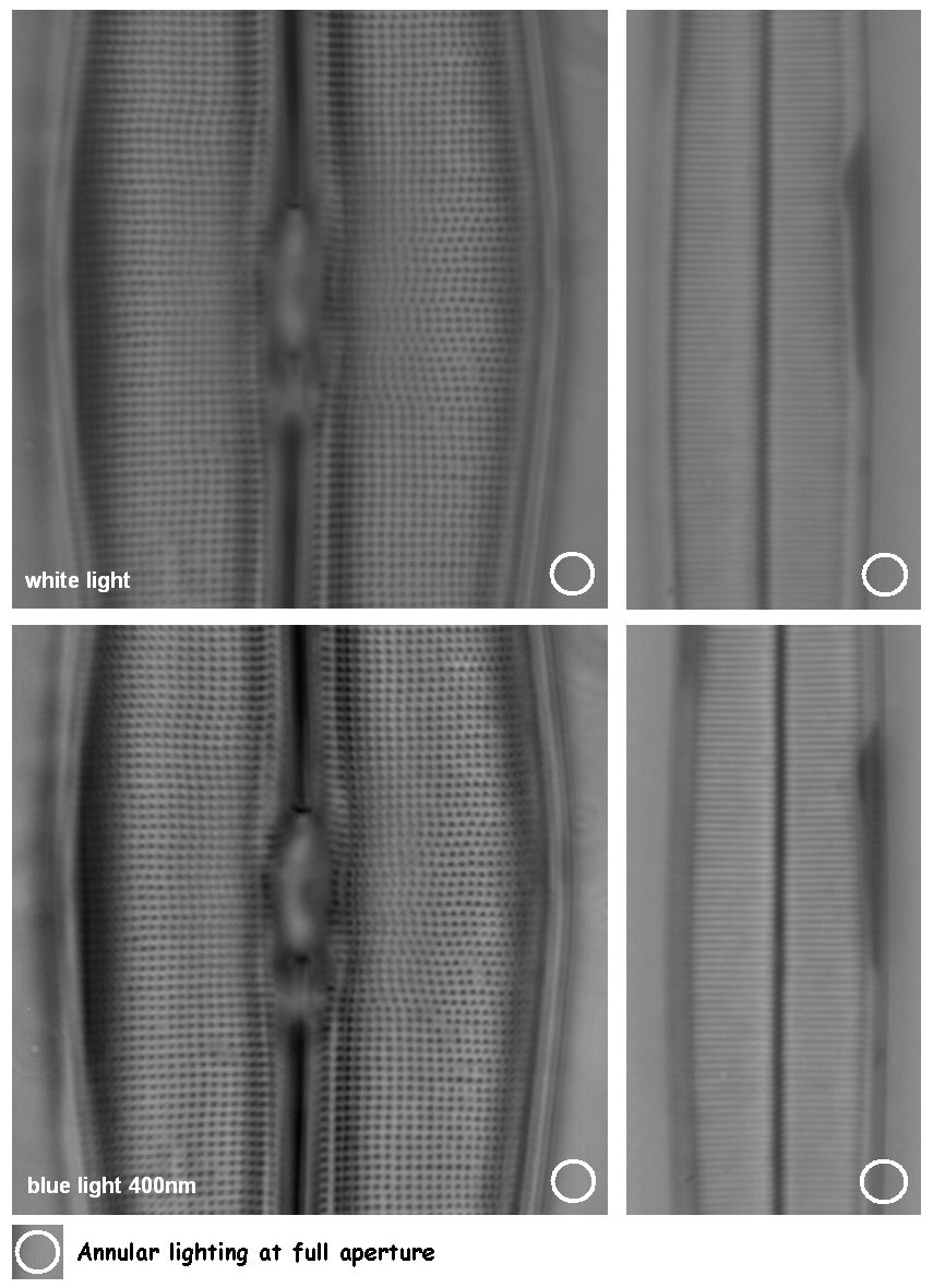
Figure 8. Annular lighting gives no shadowing effect and therefore specimen orientation is not critical. The use of a deep-blue filter for imaging gives an extra boost to the performance.
That blue light gives higher resolution is a well known fact. Unfortunately, wavelengths below 440 nm (blue) are visually hard on the eye. The use of a digital camera circumvents these visual problems and imaging quality can therefore be boosted by simply inserting a deep-blue filter immediately before imaging (figure 8).
The ultimate boost in contrast enhancement can be had by the combination of annular lighting and polarized light (figure 9). The strongest contrast enhancement is possible by placing the specimen between crossed polarizers. The pores in the interstriae of Amphipleura pellucida can then be made visible, which is right on the edge of the theoretical limit of resolution.
The explanation of this enhancement effect is not entirely clear but might possibly be explained by a darkfield effect. Direct (undeviated) ‘background’ light is filtered out while light that has had an interaction with the sample is scattered and depolarised, and therefore can pass the upper polarising filter.
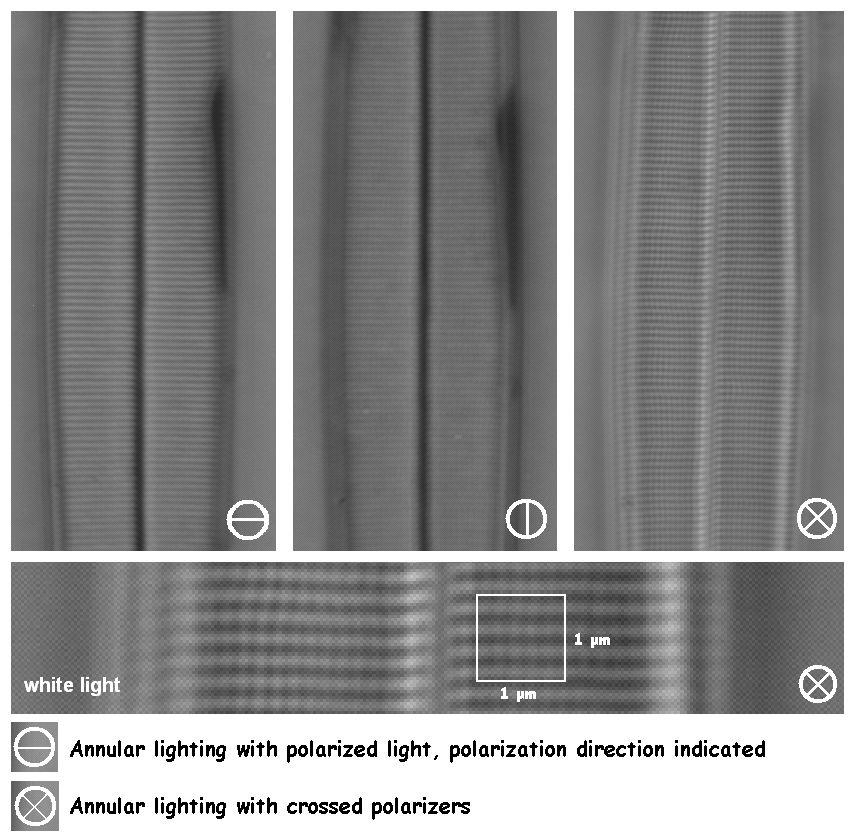
Figure 9. Annular lighting combined with polarized light is capable of showing details to the theoretical limit of resolution. The lower image is an enlarged and slightly contrast stretched portion out of the upper right image.
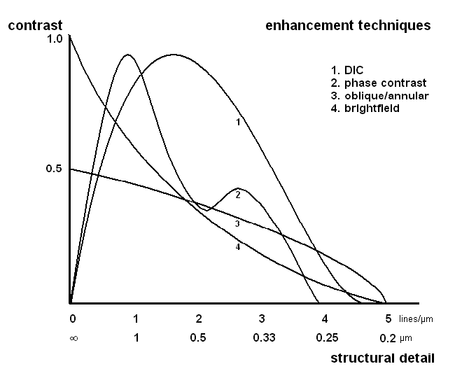
Figure 10. The generated amount of contrast plotted against size of the structure for each of the different modes of illumination. Calculated for an objective with NA of 1.3 in blue light. Adapted from Molecular Expressions.
Conclusion
With all illumination methods in traditional light microscopy, contrast decreases to zero when the diffraction limit of around 0.2 μm is reached. However, when approaching this limit there are obvious contrast differences between the different contrast enhancement-modes of illumination. There is however not one ‘best’ method, the right choice is determined by the level of silicification and the resolution range needed in order to show details. A good quality brightfield condenser should ideally be the start of any identification. If ultimate resolution is needed, an oil immersion darkfield (cardioid) condenser forms an inexpensive aid to gain the ultimate in contrast from the finest of diatom details. In tandem with a brightfield condenser, it outperforms most phase and interference contrast sets at a fraction of the costs.Technicalities The same diatom test slide from Klaus Kemp was used for all comparisons (www.diatoms.co.uk). Diatoms were mounted in Z-Rax (RI ca. 1.70). For brightfield, an Olympus 60x/1.4 SplanApo objective was used, for phase contrast either a Leitz 100x/1.32 Fluotar Ph or a Leitz 90x/1.32 apo Phv, both used with the Heine phase condenser. For DIC, the Leitz 100/1.32 Fluotar Ph was used on a Zeiss DIC system with oiled 1.4NA condenser. For annular lighting, an oiled Olympus darkfield condenser DCW1.2-1.4NA was used with a Zeiss planapo 100/1.3. For imaging a Tucsen ½” cmos camera was used, either a 3Mp colour version via the supplier's 0.5x eyepiece adapter (BF, phase and DIC images), or a 1.3Mp monochrome version for annular illumination, via 1.5x Olympus relay optics. Images are taken at the default settings of the camera with white (halogen) light, unless otherwise specified.
Acknowledgements
Peter Höbel kindly provided the background for these pages, which are electron microscopical (FESEM) images of the in- and ouside valve of Amphipleura pellucida. Peter also has very fine examples of the use of UV-light for imaging of diatoms, interested readers are urged to look at his webpages at http://www.mikroskopie-ph.de/ Also thanks to Christophe Brochard for help with figure 3.
Osama Oku 2004. A new method for visualization of diatom striae by using annular illumination and polarized light. Bull. Plankton Soc. Japan 51(1): 25-33 (in Japanese; Abstract and images captions in English, link courtesy of the paper author).
Maksymilian Pluta (1988-9), Advanced Light Microscopy Vol. 1&2. Elsevier, Amsterdam.Comments to the author are welcomed.
Editor's note: Articles on creating many of the techniques discussed above can be found in the Article Library in the Lighting / Techniques section
Published in the April 2009 edition of Micscape.
Please report any Web problems or offer general comments to the Micscape Editor .
Micscape is the on-line monthly magazine of the Microscopy UK web site at Microscopy-UK
©
Onview.net Ltd, Microscopy-UK, and all contributors 1995
onwards. All rights reserved.