Repairing a pre-owned Shandon embedding unit
Yvan
Lindekens, Belgium.
Embedding
units (as the name implies…) are used to embed samples in paraffin wax prior
to sectioning on a microtome.
Those of you having some experience with paraffin embedding know the problems that can be expected during embedding: everything needs to be at close hand and one has to work very fast to prevent the wax from solidifying during the process. Only a few seconds after the incubator is opened, the top layer of the paraffin begins to solidify, making it necessary to wait some minutes after every sample untill the wax has melted again. Once the wax is poured in the embedding form, the bottom layer begins to solidify, making it difficult to orientate the sample properly, the pair of tweezers are building up a thick layer of wax very fast, making it necessary to dewax them using a flame and so on, and so on.
When
one only has to make a few occasional blocks, it's not that much of a problem,
but when you want to embed lots of samples or when multiple samples are to be
orientated and embedded in a single block, an embedding unit comes very handy!
That’s why those units are standard equipment in histological and
histopathological labs, where hundreds of samples per day need to be processed.
After all, an experienced histology worker is required to embed some 50 – 60
“unproblematic” samples per hour.
Needles to say that embedding units are rather expensive.
The
workflow when using an embedding unit looks something like this:
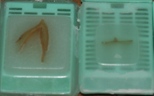
A
casette containing one or a few samples is taken from the heated tissue storage
cabinet and
brought in the -partially filed with molten wax- cassette workig area. A
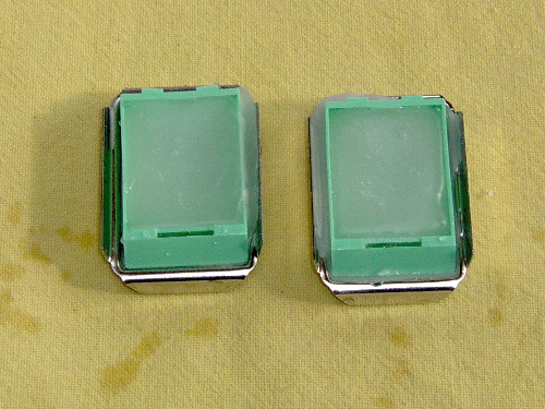
suitable mold for the sample is chosen from the preheated molds in the mold
cabinet and placed on the hotplate under the paraffin dispenser outlet. Some wax
is poured in the mold and the sample is added and orientated as required.
It
looks like a lot of work but in reality the entire procedure only takes some
seconds once you get used to it. See a movie showing the method here
(opens in new window).
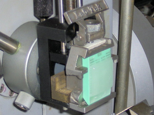
Notice that the tissue cassettes are used to contain the specimens during the entire process of fixation-dehydration-clearing-paraffin infiltration-embedding-sectioning: once the blocks are ready they're mounted using a cassette clamp fitting the microtome as can be seen in this example:
A
few weeks ago I bought a used Shandon “Histocentre 2” embedding unit “as
is” trough eBay. I finally paid 501.99 Euro for it. A bargain, as these units
costs second hand at least some 4 000 Euro’s, but nevertheless a lot of money,
especially in these harsh times of economical crisis.
Anyway, I picked it up a few days later in Germany. The seller demonstrated the unit briefly: it powered up.
A brief description of the unit and some pictures:
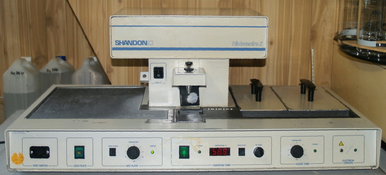
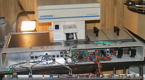
General view of the Shandon “Histocentre 2” embedding unit. The front panel contains the temperature controls for hotplate, paraffin tank and storage compartiments. On the far left a foot pedal can be connected to control the paraffin dispenser which is normally controlled by pushing the black plate behind the wax outlet. On the far right a connection for an electrically heated forceps
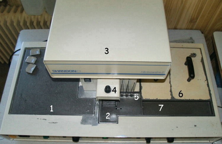
| 1. Cold plate: | factory set at about -10°C, can store some 60 blocs when using standard histology molds/cassettes |
| 2. Hotplate: | adjustable from ambient temperature up to some 80°C - 90°C |
| 3. Paraffin tank: | > 5l, temperature adjustable between 45°C - 75°C |
| 4. Paraffin dispenser: | wax flow rate adjustable with the black dispenser jet |
| 5. Forceps warmer: | for 4 forceps, temperature dependant on hotplate temperature |
| 6. Storage compartiments: | adjustable from ambient temperature up to some 80°C - 90°C |
| 7. Cassette working area: | temperature depends on temperature of both storage compartiments and hotplate |
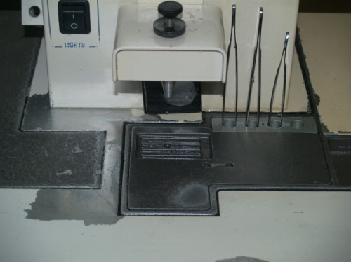
Paraffin wax dispenser outlet, hotplate and heated rack for tweezers. Part of the cold plate is just visble on the left
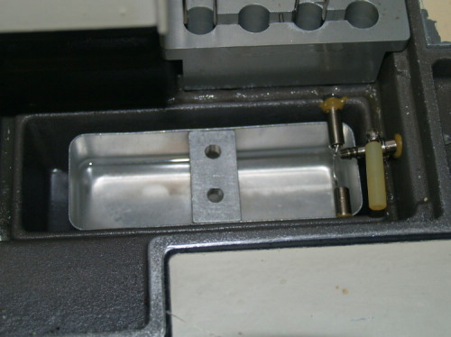
Underneath the hotplate there's a small jar to collect molten wax from the hotplate and to drain used wax from the cassette working area (notice valve on the right)
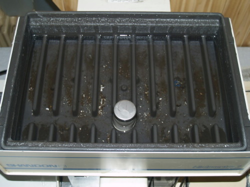
Paraffin tank, could use some cleaning...
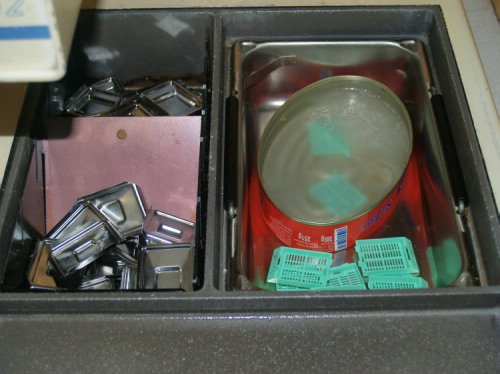
Base molds and tissue storage compartiments. Underneath those, part of the cassette working area can be seen
Once
home again and after setting up the unit I quickly noticed that there was
something wrong, as the hotplate only warmed up to some 52°C, far below the
melting point of the wax I use (56°C – 58°C), in fact far below the melting
point of about any paraffin wax on the market.
According
to the scarce information I could find on the Internet (Thermo Belgium didn’t
bother to answer my request to buy an instruction manual), a “typical
operating temperature” of the hotplate should be some 60°C – 70°C. After
all, the purpose of the hotplate is to keep the wax fluid during orientation and
embedding!
(see about the only information on the use of the Histocentre 2 I could find on the internet here (opens in new window)).
Something
was definitely wrong and I decided to try to repair it myself.
Now
I’m no field service engineer nor an electronics repair man, but at least I
have some basic knowledge on electronics: I know more or less how a resistor, a diode, a transistor and a FET works and I considered that enough to
give it at least a try.
At
first I would have a brief look only for something obvious: a loose wire, a
blown fuse or something like that.
A
close look at the unit didn’t reveal external fuses so I decided to open it up
“a bit”. I removed the front panel. Just to have a look.
Partially dismantled…
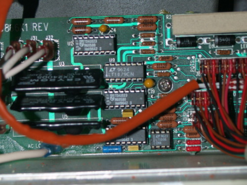
Partial
view of the well made main circuit board behind the front panel, revealing
readily available standard components. Integrated circuits easily replaceable
without (de)soldering. Notice bridge rectifiers and several TDA 1023 triac
controlling circuits
There were fuses protecting the heater circuits and those turned out to be okay:
Once there, it didn’t take that much trouble to find one of the heaters of the hot plate, as it was readily visible:
I measured it’s resistance: 1 070 Ohm. Given the fact that it consisted of 2 resistors wired parallel, that came close to the standard value of 2 200 Ohm per resistor. I followed the wires up to the circuit board. Once there, I connected my meter, powered up the unit, set the temperature control at it's maximum and I measured the voltage: 227V, let’s say: mains voltage, 230V. According to Ohm’s law that would result in a current of 0.215A thus a power consumption of 49,45W, let's say 50W. To keep things simple I didn't take into account that the heaters are powered using a proportional temperature regulation.

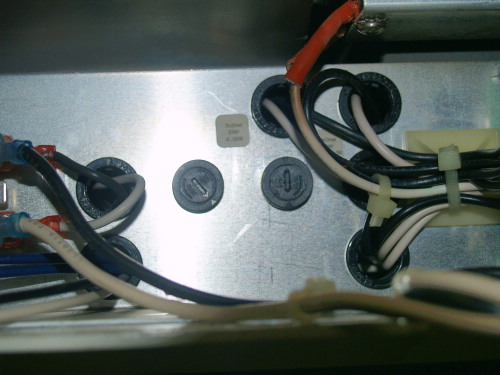
Close-up view of the circuit board. “H.P.” means connection of one of the two heaters of the hotplate
It
took me some time to locate the second heater of the hotplate as it was not
visible at first. I removed the panel bearing the main circuit board behind the
front panel, removed (after careful labeling) some wires, enough to be able to
move the panel a bit, so that I could carefully search with my hand the second
heater. I felt it, I could even loosen one of the two screws holding the heater
in place, barely able to move my hand…
I
began to think that I had missed something: if there would be components in the
unit liable to sudden dead, thus demanding servicing, it would be the heaters,
as these are subjected to thermal stress all the time…
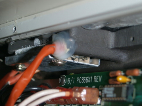
And
than it struck me: although I had inspected the unit very carefully, there was
one part I didn’t inspect that well: the bottom side! Sure, I had a brief
glance shining with a torch between the table and the bottom side of the unit
but I didn’t saw that much as some steel supporting bars were blocking the
sight…
As I wasn’t that eager to place the unit upside down on it’s paraffin reservoir, that way subjecting the vulnerable compressor of the cooling plate and its piping to extreme forces, I placed the unit between the table and some banana boxes to find a small entry underneath the second heater. I released the two screws holding it in place, giving me unlimited access to the heater! That one was as dead as dead can be. I assumed for arguments sake that the hot plate should be warmed up by two identical heaters.
Dead heater from the backside of the hotplate
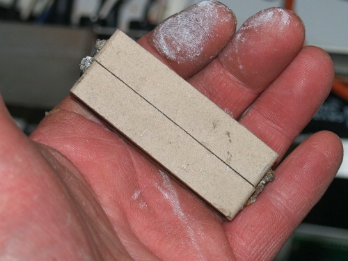
At first I thought that these heaters were only plain, standard cemented power resistors, but a glimpse at a few electronics catalogues learned that those cemented resistors are only available for a power consumption of 10W maximum.
As it wasn’t that much of a problem to use slightly larger resistors I decided to try a regular power resistor 1000W/50W. It works fine, giving a temperature range from ambient temperature up to some 90°C.
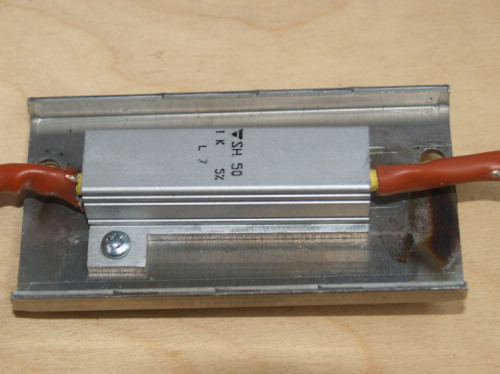
Replacement resistor
Mission accomplished!
All comments to the author Yvan Lindekens are welcomed.
Microscopy UK Front
Page
Micscape Magazine
Article Library
© Microscopy UK or their contributors.
Published in the April 2009 edition of Micscape Magazine.
Please report any Web problems or offer general comments to the Micscape Editor.
Micscape is the on-line monthly magazine of the Microscopy UK website at Microscopy-UK
© Onview.net Ltd, Microscopy-UK, and all contributors 1995 onwards. All rights reserved. Main site is at www.microscopy-uk.org.uk with full mirror at www.microscopy-uk.net .