Introduction to the Optical Microscope by Ron Neumeyer, Vancouver, Canada |
Introduction
In the early 1930's a compound microscope rolled off the "assembly" line at the E. Leitz factory in Germany. Purchased by a country doctor in Nova Scotia, Canada, it lay in its field case, largely unused, for more than fifty years. Fortunately, while living in Nova Scotia, I was able to wangle it from the hands of the good doctor's son (traded a B&L binocular scope - he wanted to view with both eyes). No doubt it appears "old fashioned" to many modern microscopists. Nevertheless, its optical and mechanical pedigrees are found in many of the sophisticated, ergonomic stands of the 1990's. Let's examine that pedigree more closely.
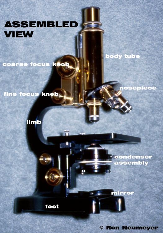
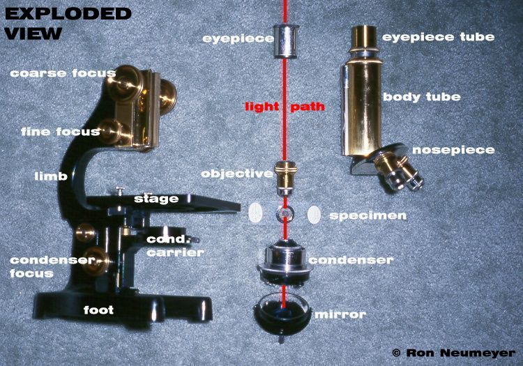
The Leitz microscope is pictured here in two views, assembled and unassembled, or "exploded". As these pictures illustrate, a compound microscope is a masterful integration of optics and mechanics, a perfect example of that old cliché, "the whole is greater than the sum of its parts"!
In a compound microscope, glass lenses are used to both magnify and properly illuminate the subject. These lenses, and their mounts, form the microscope's optical system (picture 2 - centre). However, even the best optics in the world are useless if their alignment is wrong, or if they cannot be delicately adjusted to accommodate characteristics of the viewer and subject. These, and other non-optical requirements, are met by careful design and manufacture of the microscope stand and body. In the following paragraphs key features of each are discussed.
The Optical Components
We can begin our journey by following the transmitted light optical path - the red line in picture 2 (below). For the purpose at hand, the starting point is the mirror, although many modern stands have base illuminators instead of a mirror - but the net result is the same. A typical microscope mirror will have one flat and one indented, or "concave" surface. If your scope includes a condenser then always use the flat side - if not, use the flat side with objectives 10x or below, the concave side with objectives above this magnification. (Unfortunately, to get high quality images from objectives of more than 10x a condenser is essential.)
The first optical device the light beam encounters is the
condenser. Although not evident in the picture, prior to entering
the bottom condenser lens the beam passes through a filter
carrier and an adjustable iris diaphragm, referred to as the
"aperture diaphragm".
A number of different colour filters are available. They modify
the spectrum of the transmitted light beam for one purpose or
another. For example, many microscopists use a blue
"daylight" filter with tungsten lamps for a more
"natural look". (Tungsten lamps tend to produce
excessive amounts of red light, especially when dimmed with a
voltage control.)
The condenser optics refract (bend) the incoming "bundle" of light rays, changing its shape from a tube to a cone. When properly adjusted this cone provides intense, even illumination of the subject. The aperture diaphragm controls the diameter of the light "cone" exiting the top element of the condenser. Theoretically, the aim is to provide a cone diameter at the plane of focus that exactly matches the objective's aperture. In practice however, the diameter is often reduced slightly in order to provide a compromise between resolution and contrast. This device must not be used to control light intensity, a surprisingly common practice. Reducing light intensity by this method will produce high contrast, but low resolution images.
The light beam then passes through the specimen (i.e., whatever is on the glass slide) and enters the front element of the objective (literally the lens system nearest the specimen, or "object"). The objective assembly is the heart of the magnifying portion of the microscope. From the time the compound microscope was first assembled, in the late 1600's, until the beginning of the 19th century optical deficiencies ("aberrations") in the objective caused numerous "misinterpretations" of what was being observed. As a result, scientists of the day did not hold the compound microscope in high regard. During this period they considered the simple microscope to be much more dependable. (Fortunately, the compound microscope remained a favourite of the rich, who used it to explore and to entertain. In a sense, they provided the funds needed to support the work that finally resulted in making it an essential scientific device.)
By the end of the 19th century, everything had changed. Most makers offered "corrected", multi-lens objectives ranging from those with moderate corrections, "achromatic", to the optically sophisticated, essentially fully corrected "apochromatic". These improvements were achieved by combining different types of glass and by using newly discovered principles of optical design (rather than trial and error). Needless to say, with objectives, as with most things today, you generally get what you pay for. An apochromatic objective costs about five times as much as its lowly sibling, the achromatic objective.
Most 20th century objectives have some useful information engraved on the barrel. Of special importance is the magnification and numerical aperture, or NA, of the lens. Today, these are usually stated together. The engraving on the barrel of the 10x achromatic objective, shown in picture 2, is "10/0.25"(magnification/NA). A similar apochromatic objective would have a higher NA and might read "10/0.32". Other optical features of the objective may be denoted using letters, such as - Plan, or Pl for flat-field - Fl or Neofluar (Zeiss) for fluorite and Apo for apochromatic.
The magnified image formed by the objective, the so-called primary image, is further magnified by the optical assembly nearest the eye, the eyepiece. An eyepiece does little to the primary image other then make it visible to eye. The resolution of the microscope is strictly limited by the illuminator-condenser-specimen-objective relationship. However, high quality eyepieces provide better colour correction and a wider, flatter field of view, especially with highly corrected objectives. In addition, a good eyepiece can dramatically improve viewing comfort!
Optics alone will not make a good scope. In my opinion, for most scopes, what you see on the outside is what you get on the inside. In other words, if the stand and controls are substandard (or it shows clear evidence of abuse), then the optical components cannot deliver optimum resolution (the quality of which may also be suspect in such a stand). Support and manipulation of the optical assemblies (and specimen) must be first-rate or your money is wasted. (Buy the best stand possible, optics can be upgraded later.) Let's have a look at the mechanics of the old, "solid" Leitz.
The Body
The right-hand side of picture 2 shows the microscope body, which is designed to hold the magnification optics. At the bottom is a revolving nosepiece, or as it is sometimes called, the "objective changer". Surprisingly, this convenient device was not commonly available until the end of the last century. Prior to that, if you wanted to change objectives it was necessary to remove and screw each in separately. Needless to say this afforded an excellent opportunity for dust to enter the barrel, and, the most heart stopping moment of all, watching a prized objective head for the lab floor! (Although early changers stopped the loss of objectives due to dropping, they did not include the circular dust cover, and hence the dust problem remained. It took several years before all makers included fully enclosed nosepiece as standard items.)
Introduction of the nosepiece forced manufacturers to produce objectives that remained in focus as they were rotated into position. Objective series of this design are said to be "parfocal". Anyone considering an older scope should verify that the objectives are parfocal, as this is a great convenience. Older stands with mixed maker objectives may not be parfocal, which means that not only must you refocus each one, but there is a danger of striking the slide surface when switching from low to high power.
The Stand
The stand supports the body tube and substage assembly, as well as the specimen. Picture 2 illustrates the main components of a typical stand prior to about 1940. Since then they have changed dramatically, although the basic elements remain.
The base, or as it was once called, the "foot", provides stability to the instrument. The foot has undergone every conceivable alteration over the years in an effort to find the ideal design, in terms of function and low production costs. The Leitz has a "horse shoe" foot (resembles one in cross section). The upper portion of the stand rotates about an axle supported by pillars (the brass lock nut can be seen just above the condenser focus knob). In this case the pillars and foot are cast in one piece.
This stand allows the body tube to be pivoted, or inclined, for comfortable observation. However, the stage also tilts, a most annoying feature when viewing liquid mounts. This design has now been largely abandoned in favour of a body with a 45 degree eyepiece tube(s), and horizontal stage.
The architecture of the Leitz limb harkens back to the mid 19th century and, with several improvements, persists in student scopes today. It has much to recommend it. The "C" shaped limb allows one to manipulate a large petri dish or other stage object, while keeping the body tube and stage in rigid alignment. In addition, it provides the perfect hand-hold when moving the scope around (with the other hand under the base - just in case).
The lower end of the limb terminates in the tailpiece, which has a hole for accepting the gimballed mirror (via a pin at the base of the mirror fork). Also, on the tailpiece is the rack gear (gearing is explained later in this article) and guide for the condenser carrier (picture 2). In this picture, the carrier has not been removed. The condenser body slips into the carrier collar and is secured in place by a small set screw. The geared pinion drives the rack and allows one to critically focus the condenser (via the "condenser focus" knob).
The stage is secured to the top of the tailpiece. Set perpendicular to the light path, it provides a flat, level surface for the specimen. In this microscope, the specimen slide is held down with spring clips and must be moved about by hand. A better arrangement is to install a "mechanical stage". This type of stage allows the slide to be moved in the x and y directions by rotating small knobs acting on gear assemblies. The end result is very delicate, very delicate movement of the specimen. (Although not very commonly found today, but surprisingly effective, is the so called "gliding" stage. The stage deck rests on a support plate which is coated with grease. The entire deck can be moved in any direction by light hand pressure.)
At the opposite end of the limb is the mechanical assembly that carries the body tube (picture 2). The "rack", a short steel bar with several dozen precision cut diagonal grooves, is screwed to the side of the tube. The rack slides into a guide notch and engages the circular pinion gear, which is fastened to the axle between the two coarse focus knobs. Turning these knobs rotates the pinion gear, which in turn acts on the steel rack moving the body tube rapidly up or down, perfect for preliminary focussing.
In this stand, the coarse focus pinion and body tube rest in a block of brass which can also be moved up and down. This is done by means of the fine focus mechanism, is very sophisticated gear assembly that cannot be adequately described here. However, by means of the two small knobs located below the coarse focus control, the operator can adjust the focus with great precision (i.e., very slowly). Most microscopists use the fine focus 90% of the time.
The focus design illustrated by this Leitz stand has one serious shortcoming, the entire weight of the body tube and coarse focus block must be borne by the surprisingly delicate fine focus mechanism. For observational purposes a well made microscope will provide decades of service using this design. Unfortunately, on poorly made scopes, or ones that have been abused, this is one of the first areas to show failure. Repair is often difficult, or on older stands, impossible. Always pay very close attention to the fine focus system when inspecting a used scope. There should be no rebound effect, and no drift in focus. If this is noticeable - look for another instrument.
Many modern scopes have abandoned limb mounted focussing altogether. Instead, the focussing system acts on the stage and substage (they move as a unit). The body is secured to the top of the limb. The beauty of this arrangement is that one can easily change the viewing head and nosepiece. Adding heavy cameras and other instrumentation presents no mechanical problems (although optical corrections can still be negatively impacted).
Further Information
This concludes the overview of the optical microscope. However Micscape has a vast archive of related articles. Browse the 'Techniques' section in the Article Library (link below).
Comments to the author Ron Neumeyer welcomed.
Editor's note
Also visit Ron's Light Microscopy Forum website which contains a variety of resources for the microscopist.
Published in the April 1999 edition of Micscape Magazine.
Please report any Web problems
or offer general comments to the Micscape Editor,
via the contact on current Micscape Index.
Micscape is the on-line monthly
magazine of the Microscopy UK web
site at Microscopy-UK