John Delly's 'Photography Through
The Microscope', Kodak Publication P-2, Ninth Edition 1988, describes the
many ways of attaching a camera to the microscope for photomicrography.
I consider this book to be the standard reference for anyone interested
in the operating principles of the light microscope and photomicrography.
Projection into a camera back mounted
on a rigid macro stand like the Leitz Aristophot or Nikon Multiphot was
the method used by John for photomicrography when he was on the staff of
McCrone
Associates. This method minimizes the effect of camera vibration because
there is no mechanical connection but only a light trap between the microscope
and the bellows of the macro stand. A massive and rigid stand absorbs the
forces from a 35 mm camera focal plane shutter without shaking the microscope.
To further minimize vibration, a leaf shutter can be used at the mouth
of the bellows of the macro stand with the 35 mm camera set on bulb.
I have previously used a very rigid
stand I built from a modified tool makers lathe for photomacrography and
more recently also for photomicrography, as shown in the supplementary
page for my darkfield article in
the April 2001 issue of Micscape. I have not found a need for a leaf shutter
with this massive and rigid stand. I recently disposed of my darkroom equipment
but kept the enlarger stand. I chose to keep the stand because it can serve
as a copy stand and also to hold a camera back for photomicrography. Since
I now have two student microscopes for family use, having a second stand
makes sense for this reason and also because it is far more portable than
the heavy photomacrography stand.
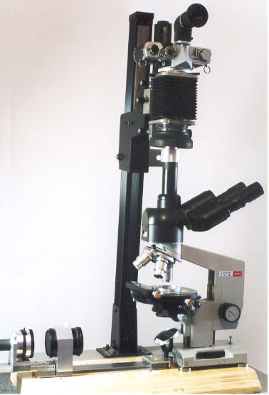
Figure 1 shows the enlarger stand
with the vertical tube of trinocular head on a Biolam (Multiscope) projecting
into an OM-4 camera back mounted on an Olympus bellows. I use the OM photomicrography
1 - 12 focusing screen in the camera and view the screen through an Olympus
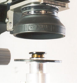
Varimagni Finder. An Olympus plastic cover with bayonet lugs fitting the
lens mount in the bellows was bored out and a flexible lens hood was epoxy
bonded to make the bellows side of a light trap. A black plastic disc on
the trinocular vertical tube nests inside the lowered hood without touching
the inside of the hood. These details and the projection eyepiece are shown
in Figure 2.
The projection eyepiece is a LOMO
7X measuring eyepiece with the reticle normally removed and the eye lens
adjusted outward to form a real image at the camera film plane. The reticle
can be reinserted when a scale and cross lines are needed in the photomicrograph.
I first had to add an extension to the photo tube adapter of the trinocular
head so that the eyepiece reticle would be simultaneously in focus with
the image viewed through a focused reticle eyepiece in the binocular viewing
system. The black plastic disc of the light trap sits on a narrow flange
of the extension made for the vertical tube. (The disc is not fully seated
in Figure 2).
Since many of the readers may own
LOMO Biolam microscopes, some details about the LOMO optics could be helpful.
I have found that the short mount 160 mm tube length LOMO objectives require
the same compensating eyepiece system as previously used by Carl Zeiss.
I normally use a Zeiss 12.5X kpl eyepiece for viewing with a drawtube in
a monocular system. The projection eyepiece I use for photomicrography
with the monocular system is a Zeiss 8X kpl measuring eyepiece with the
reticle removed and with modifications to increase the separation of the
eye lens from the field lens. The Zeiss kpl eyepieces correct for both
difference of chromatic magnification and flatness of field. The magnification
changer lenses in the LOMO trinocular head correct for flatness of field,
so the image is then sharp from center to edge when using the LOMO eyepieces
but not the Zeiss kpl eyepieces. The LOMO eyepieces correct only for difference
of chromatic magnification.