|
|
May be the word 'electronic' is a little confusing: indeed it's not a REAL electronic microscope, because electron beams aren't easily usable by amateurs. However the term is justified: all its components, lens excepted, are electronic devices: LED for lighting, CCD (webcam) to take pictures and the most amazing....: electronic focusing!! Another feature of interest: it's a cheap microscope you can make yourself and experiment with. |
|
|
|
But what is the use of a such microscope: it's an inverted design, the objective is located UNDER the slide and illuminator above (long distance working distance). So you have more room on the stage to put large vials containing water or culture box and to access the cells for handling for example... Besides, objectives are never in contact with liquid... |
|
|
|
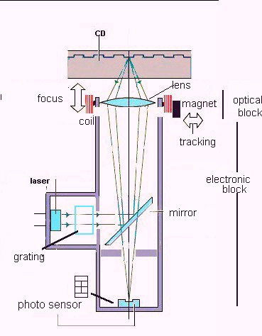
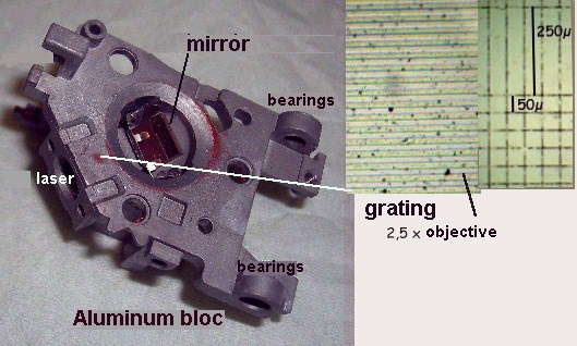
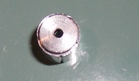
But how will we make this microscope? You can obtain the main device from a discarded CD-ROM reader (or reader/writer**) which you can find for free in computer repair shops for example. When you disassemble such a component, you can see, near the CD axis, an assembly of 2 main parts: first an optical device, including a little plastic lens which can move up/down and front/rear using 2 groups of coils. Secondly and below the first, an aluminum block which includes one infrared laser diode lighting the lens through a semi-transparent mirror and at the bottom of the block, an optical sensor used to read the CD and ensure tracking. Note: often, in the laser light path, is located a little cylindrical part which is a diffusion grating. You can see an aspect of the grating in the righthand picture below (with a scale added for comparison). You can use the grating (3 mm diameter ) like a slide micrometer! The aluminum block has bearings which can slide on two steel rods when it follows CD tracks. ( ** Probably a discarded music CD or DVD player ... will work well too.) (Safety note: the CD-ROM device must not be powered up when disassembled as the laser maybe dangerous to view.) |
|
|
|
|
|
|
|
|
|
|
|
|
|
|
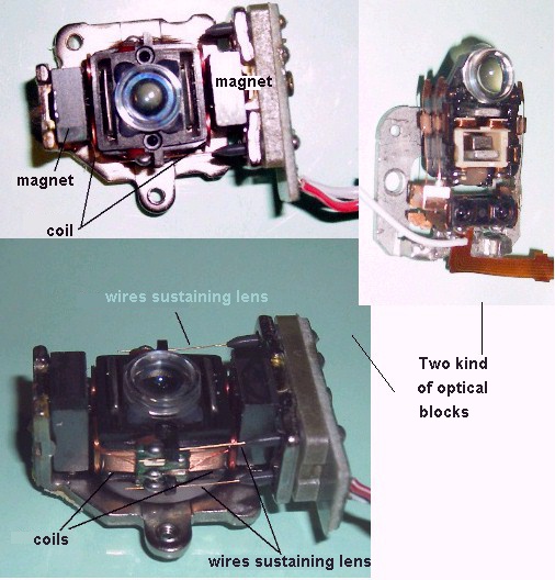
You may have already understood that the lens will be the objective in our microscope. First, you must identify the terminals which are used to displace the up/down coil, which is the 'focusing' coil. In fact the coil acts like a loudspeaker coil... |
|
|
|
|
|
|
|
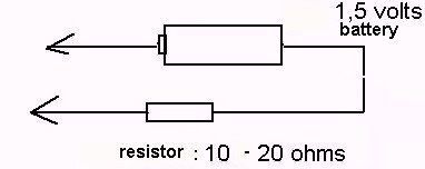
It's not difficult to make the little accessory below to test pins in pairs: when the lens moves up (or down) you have found the usable coil. You can solder - with care - two little wires on the pins. |
|
|
|
|
|
|
|
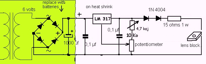
The coil resistance is around 8 ohms and working current around 100 mA: you must make an electronic circuit like that below (in fact a variable power supply!) to feed the coil. Lens displacement will be around 1 to 1,5 mm, controlled by the potentiometer. It's easier to use 2 x 4,5 volts batteries in series (9 volts), to replace the transformer, rectifiers and 1000 µF capacitor. If you want to displace the lens up AND down with the same potentiometer, you must use a bipolar power supply, and the circuit becomes more complex. |
|
|
|
|
|
|
|
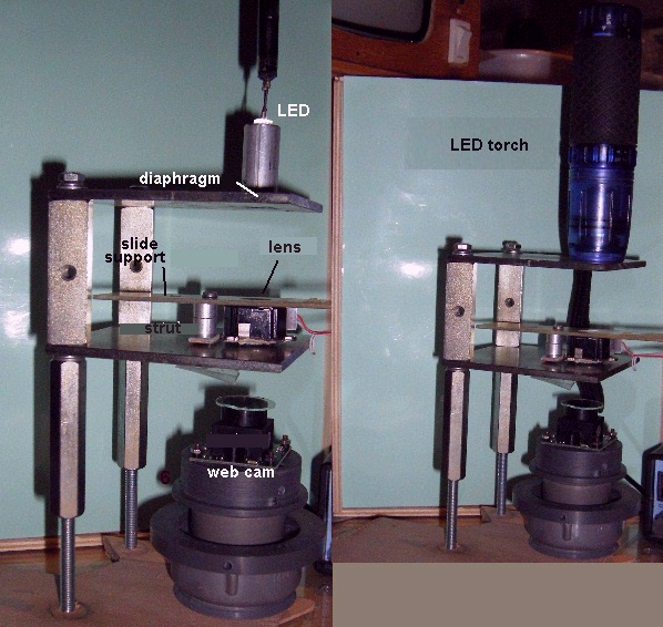
On the prototype, the slide is supported by a thin plate - here a printed circuit board - the distance between plate and lens must be adjusted with several washers on struts so that, with coil unpowered, focus is made 0,2 mm BELOW slide surface (slide thickness is often around 1,2 mm ). So you have more than 1 mm to focus on the sample. If you want to use homemade well slides (by gluing a coverslip below an 18 - 20 mm diameter tube for example), focus with the lens unpowered and the well must be made on bottom of the coverslip... Picture below is an example of design, lefthand picture with white led illumination (led located in small tube with 2 mm hole in bottom ) and in righthand picture there's an LED torch in place of the led... |
|
|
|
|
|
|
|
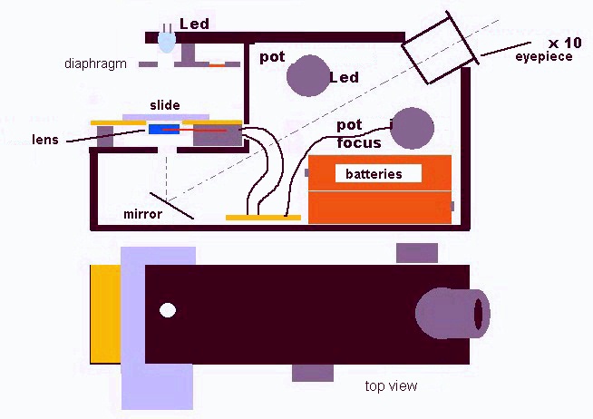
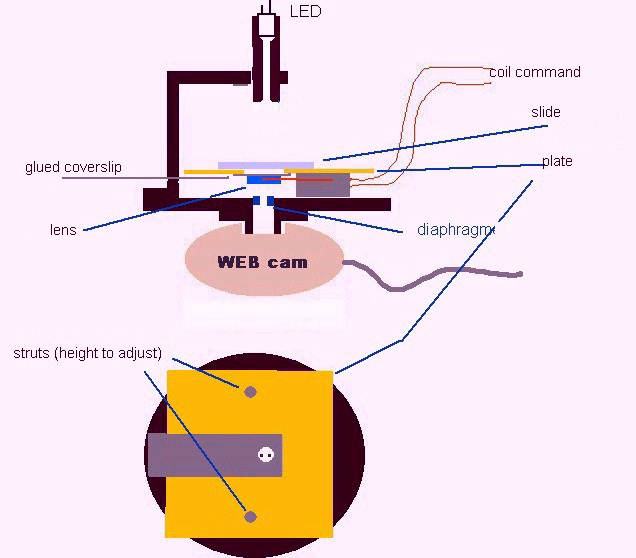
Below is a schematic of the whole microscope: some features can be experimented with, for example: diaphragms with 1,5 to 2 mm hole in front of the LED and between lens and webcam, little lens in front of the led.... The webcam lens MUST be removed: avoid dust or particles falling on the CCD surface! A coverslip lightly glued on webcam thread is useful. |
|
|
|
|
|
|
|
You can improve constrast by using a diaphragm (washer with 2 mm hole) below the lens: see picture below. |
|
|
|
|
|
|
|
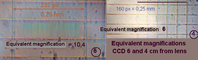
The equivalent magnification (ie: magnification of a real objective, if webcam was fitted on the 16 cm tube of a classical microscope) is between 6 times and 10 times according to distance: Lens - CCD (respectively 4 and 6 cm). A x6 magnification is quite ideal to explore quickly a sample and to pick the more interesting subjects with a micro pipette. |
|
|
|
|
|
|
|
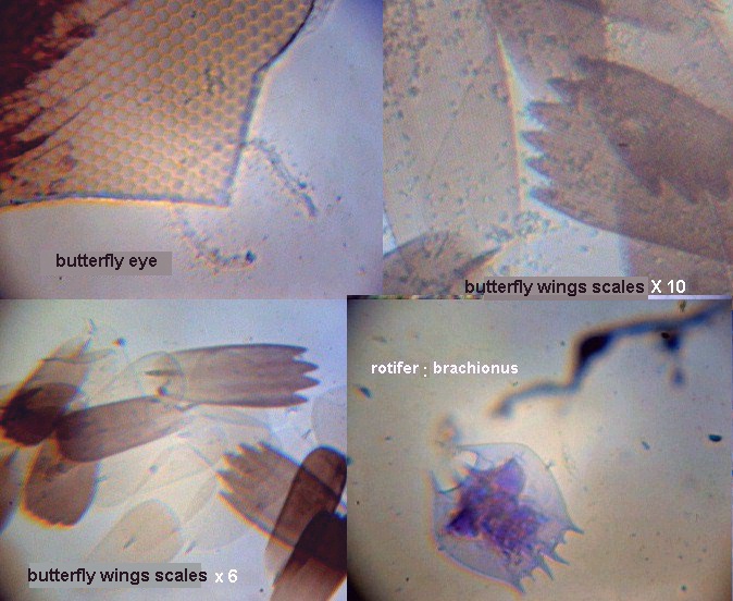
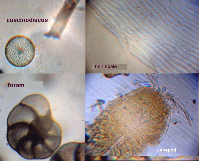
But probably you are impatient to see pictures! They are not equivalent to plan achromat objective pictures, of course: don't forget that the lens is a plastic lens!! But in the top righthand corner picture below, you can see ribs on butterfly scale! This picture is taken with x10 equivalent objective, all the others with x6 equivalent objective. Pictures are not enhanced nor retouched. Subjectsinclude those from old slides mounted in glycerin gelly, some of them are colored with methylene blue. |
|
|
|
|
|
|
|
Magnification is around X6 with CCD located 4 cm from the lens. All the CCD field of view is covered by the beam. If CCD is moved 6 cm from lens, the magnification becomes a x10 objective equivalent but beam overflow field of CCD. |
|
|
|
|
|
|
|
The results are interesting and probably can be improved if you try a more elaborate lighting assembly: for example with a small lens located 2 cm below LED: pictures taken with an LED torch are better. It's important to align correctly center of lens and CCD and be sure than lens CCD planes are parallel. If you want to improve focusing distance, you can use a bipolar power supply: in this case the lens displaces itself up and down in a range of + or - 1,5 mm and you can use deeper well slides. Note: don't discard steel rods used to guide aluminum block: you can use the block to fix the slide and move it in front of the lens (a kind of half X-Y stage!!) |
|
|
|
At this point, another idea could be developed: a portable inverted microscope, batteries powered to observe sample on land, Something like McArthur Open University microscope, but a little more rustic...It could be designed according schematic below,.... maybe a future article?! |
|
|
|
If some readers are interested in experimenting with these devices, please don't hesitate to contact me... Comments to the author Jean-Marie Cavanihac are welcomed. |
|
|
|
|
|