|
Replacing tungsten incandescent lamps. by Michael Stubbs-Race, Australia |
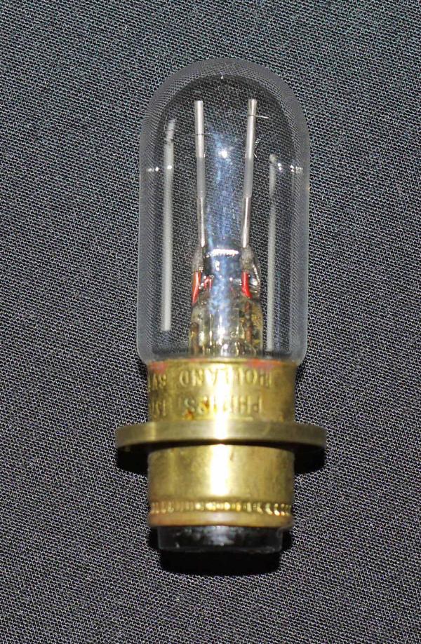
With the impending demise of the tungsten lamp, many microscopists will be wondering what expensive alternative is likely to be offered. Unfortunately, microscope lamps are not widely used in other industries, and so it may be some while before alternatives become readily available. I recently had the pleasure of dropping my last lamp, so a quick alternative had to be found.
The following is my way of adapting a 1 watt LED to a new role.
The first consideration is that our new lamp needs to fit easily into the old tungsten lamp housing. Such lamp housings usually contain condensing lenses, iris diaphragms, focusing adjustments and such like, so we really need to keep these things in place. This means that our replacement light source should simply replace the old burnt out bulb. Often an SBC type pre-focus fitting into a two pin socket.
Light Emitting Diodes (LEDs) come in a wide variety of shapes, but I chose a 1 watt model because I had one in the junk box! True it is a surface mounted device and requires a heat sink. But these lamps dont produce a lot of heat, so a fairly modest heat-sink will serve quite well. A current regulator circuit should be purchased when buying the LED and a 12 volt plug pack should complete the technical stuff. Actually, the circuit components, will work quite well with a supply of from 9 volts to around 35 volts * ; thus almost any spare plug pack will suit. Or even a battery albeit with limited life.
The first essential step, is to measure the exact position of the old lamp filament, with respect to say, the end of the brass lamp cap or base. With my lamp this was just one inch. Very convenient! This spot, is where the centre of the LED must be located.
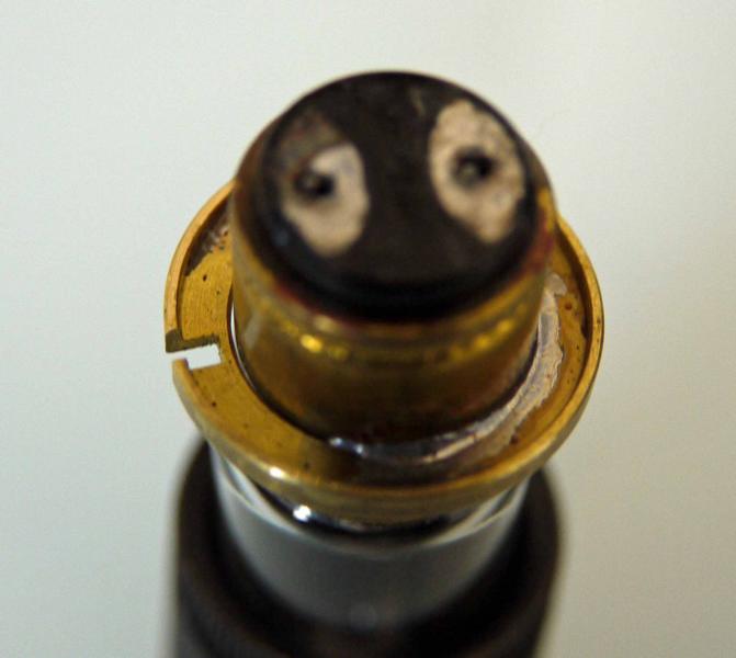
Next the glass envelope has to be removed from the lamp base, as we will construct our new system into the old lamp base. So using a soldering iron, remove the solder from the base contacts; easily done using a solder wick or sucker. Alternatively, use an old tooth brush, just quickly flick the molten solder away (dont flick it onto the dog, or the Persian carpet, and replace the wifes brush when finished !). Now if the glass is not already broken, wrap it in some newspaper or old rag, and tap lightly with a hammer. Harder if needed. Carefully remove as much of the glass from the base as possible using fine pliers or the like. The glass-metal adhesive can be very hard and may need to be ground away from the cap using something like a Dremel tool. Some of the older glass-metal adhesives could be softened in methylated spirit so a lengthy soak could solve the problem. In any event we need to get the old brass lamp base cleaned up ready for the next stage.
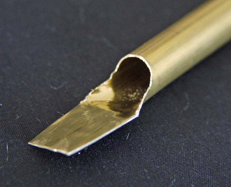
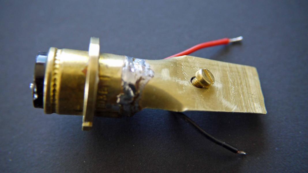
The supporting collar or heat sink I made for the LED was cut from a piece of brass tube found in a model shop. It is just under the diameter of the lamp base, and thin walled at 0.015 inches. Alternatively, it can be cut from flat sheet material; copper, brass, tinplate etc. Nothing fancy, but once cut, roll it to fit inside the lamp base. Ensure all metal is spotless clean so that the solder runs easily, and complete. In order to get the spade shape, I cut half way through the tubing, split the end and hammered it flat. Then trimmed the edges. Do all this prior to cutting to length.
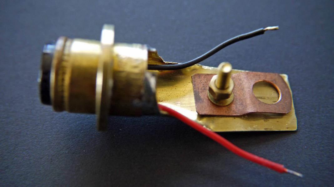
The LED is mounted by means of a single screw through a little bracket, also made from a scrap of brass. Mine was cut from a copper pipe saddle. When mounting the LED it should ideally have a spot of heat sink compound, to improve heat conductivity.
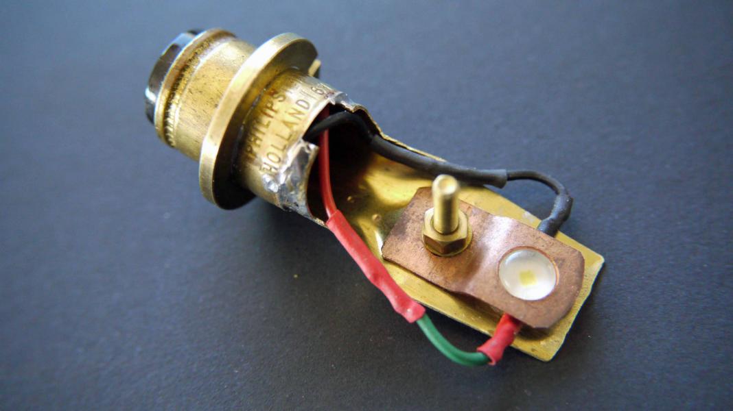
Next the LED support is placed inside the old lamp base, and soldered around the rim. Both parts are very thin, and we must not melt the solder holding the lamps pre-focus ring in place. So with a hot 60 watt soldering iron, just make small tacking spots around the base, allowing the work to cool between each tack. I held the lower lamp base, gently in a vice and ran the solder around without any problem.
Finally, the LED is clamped to the heat sink, with a dab of heat sink compound beneath it. The connecting wires soldered in place, and the new device ready to be installed. I didn't cut the LED saddle securing screw short, as it is out of sight and adds to the heat sink rating.
Now the smarter ones reading this will immediately proclaim that I have used a polarized device, without indexing the pins. Correct. But since this is a diode, if its round the wrong way, it wont light, and if correct, then it will light.
No LEDs were harmed in the construction of this light source !
Some lamp patterns use the element at right angles to the lamp axis, so the heat sink would require a tab to hold the LED in such a position, but not difficult to fashion.
· My lamp runs well with a 9 volt plug pack. However, if using a higher voltage then the current regulator will produce more heat, and so need adequate cooling.
· If using thin walled tubing, a fine pitch hacksaw blade is needed or a modelling saw.
· The glass used with microscope lamps is often quite thin, and easily cuts fingers.
The LED thermal stud is not normally isolated from either supply line, so the two wires should be kept insulated from the metalwork. Depends upon the LED maker's design.
Comments to the author are welcomed.
Microscopy UK Front Page
Micscape Magazine
Article Library
© Microscopy UK or their contributors.
Published in the August 2010 edition of Micscape Magazine.
Please report any Web problems or offer general comments to the Micscape Editor,
via the contact on current Micscape Index.Micscape is the on-line monthly magazine of the Microscopy UK web
site at Microscopy-UK
© Onview.net Ltd, Microscopy-UK, and all contributors 1995 onwards. All rights reserved. Main site is at www.microscopy-uk.org.uk .