|
by Gordon Couger USA |
 |
Click on images to view larger versions.
|
by Gordon Couger USA |
|
Click on images to view larger versions.
I am working on a prototype for a project that will be doing work digitizing images from video cameras with multi-spectral lighting. Multi-spectral lighting is a technique of looking at certain very narrow bands of light that are strongly absorbed or reflected by the substance of interest compared with a narrow band of light that remains constant and doesn't change and the ratio between the two can give useful information. One example was a sprayer that Mike Veldmen WD0CTA and I helped build for Biosystems & Ag. Engineering and Agronomy at Oklahoma State University (1) that sensed a red (R) and near infra red band (NIR). By using x = (R+NIR)/(NIR-R) the value of x was used to determine one of 16 possible settings of 4 fertilizer spray nozzles to adjust the rate of nitrogen fertilizer based on a graph made with the same machine over wheat of known history and fertilizer rates selected by two experts. In other words Dr. Stone and I ran the sensors crossways on some plots that we knew how much fertilizer had been applied to and with about 50 years of wheat growing experience between us made a look up table of how much we thought each plot need. Mike did the hardware and I did the software design and implementation.
When we tried it on actual plots of wheat, the rate of spring top dressed fertilizer was cut in half and the yields remained constant or the same amount of fertilizer could be applied and the yields increased 8% by putting nitrogen were it was needed or not putting it where there was a adequate supply.
Having tried several things that I had around that were too clumsy I asked Mike, who is very good at coming up with out of the box solutions to problems, for help. In this case he informed me I didn't need help I just needed the video camera and EPI lens back he had borrowed from me. This was a little closer than I wanted to work but the thought of having the whole thing set up on the desk top was sure intriguing so I gave it a try.
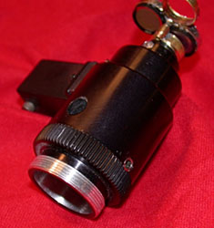
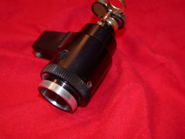
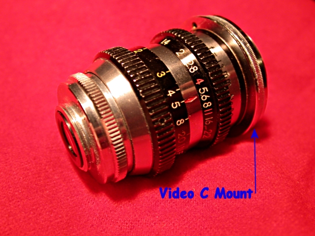
'C' mount lens for the video camera.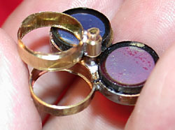
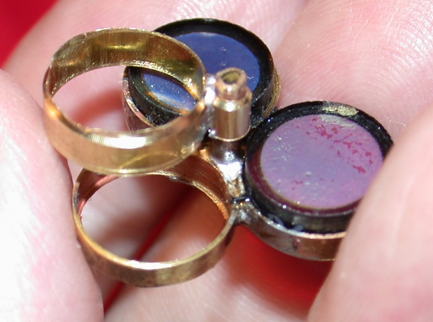
Detail of the homemade filter wheel for the 'C' mount video lens. Fig. 1 shows where it locates on the video camera.Above is the lens with a hand made filter wheel that was not practical because there was not enough clearance for the light. The incident light attachment takes a fiber and is the square projection on the far side of the lens. Unfortunately the lens has no markings so I have no idea who made it. The field of view is just less than 2 mm and the working distance was so close I couldn't get good lighting under the filters. Using the EPI illumination was hopeless because of the reflections from the filters. More on this later, there are more problems to solve first.
Taking an Axe to a Perfectly Good Microscope
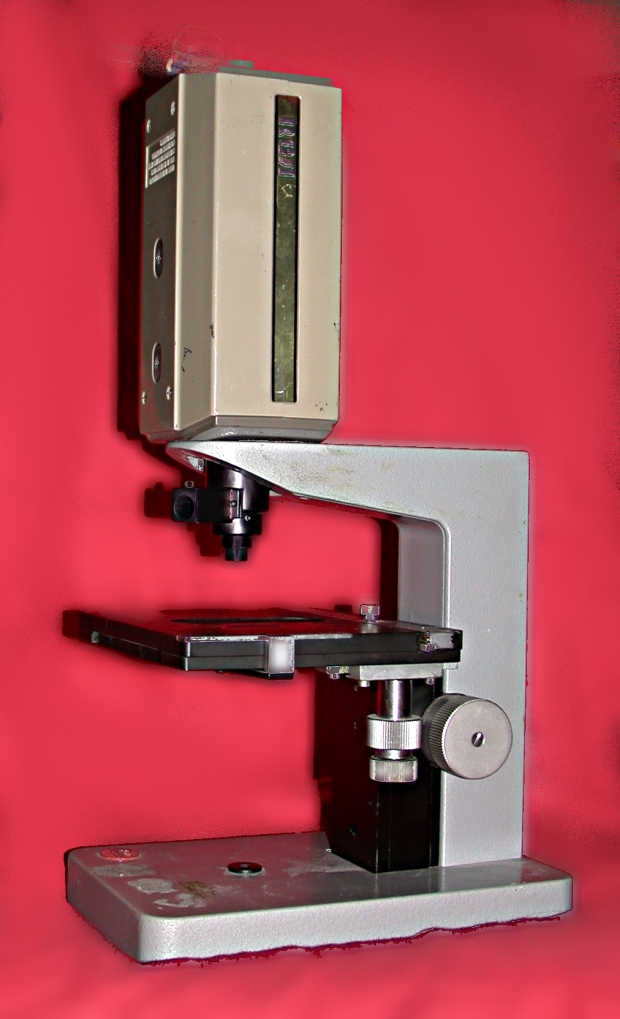
Trying to use this lens presented a problem since it acted more like a microscope objective than a video lens so I started looking around to see what I had available to solve the focusing problem. I have a Leitz SM EPI-LUX with a lovely flat top where a video camera would sit square to the world and require very little bracing to be reasonably stable. Remember this is a prototype not a finished product. The scope would almost work when the mount for the objectives and head piece were removed. There were just a few pieces of the casting in the way. These parts of the casting are not critical to any of the location surfaces of the microscope so I decided to alter the casting so the lens would fit. I would have felt more guilty about it but new Leitz stands sell for $30 USD on ebay and it doesn't effect the function of the scope in any way.
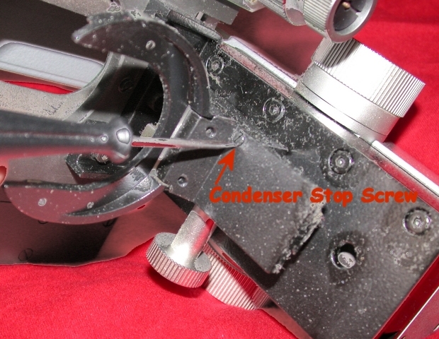
To get to the casting with a Dremmel tool the Leitz has to be disassembled. The base comes off by removing 4 Allen screws from the bottom. The only tricky part is removing the condenser fork. You have to loosen the screw that keeps the condenser from running off the end of the rack enough so that you can run it off the end of the rack. You do not have to remove the screw completely. Then remove the two screws that hold it to the stand. Then remove the three Allen screws attaching the stage. Reassemble the condenser fork with the screws that attach it to the stand (these are captive inside their holes) and tighten the screw that keeps the condenser from running off the end of the track and all the parts will be there when you want to put it back on.
Once you have the scope disassembled, mark the area you want to remove and wrap the rest of the scope with plastic and masking tape to keep the grit and metal particles out.
Grinding the Unwanted Areas Away
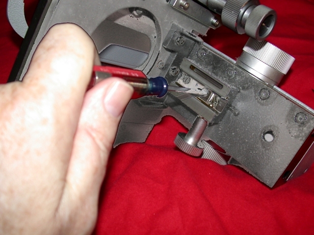
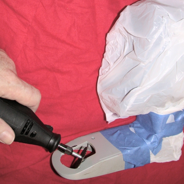
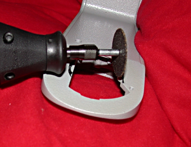
For your Dremmel tool or what ever hand-grinding tool you use, only use fiber reinforced cutting disks only. I can not stress this too strongly. The cheap disks will shatter at the least side pressure and the fiber reinforced ones will stand all kinds of abuse. Full goggles are a must. A full face shield is better and wear old clothes. The metal and grit will be thrown right into your face. The tool is used like this (figs. 5 and 6).
The areas removed do not change the functionality of the scope in any way. You can expect to see more projects using this scope in the future. It is too good a base to pass up.

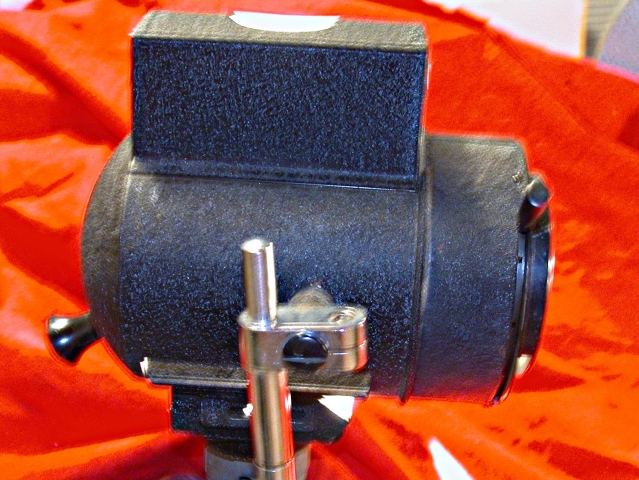
Widening the hole in the top of the microscope stand for the video camera.
The Next Try at a Solution
(double click on small images for full size ones)
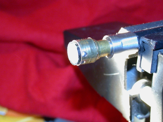
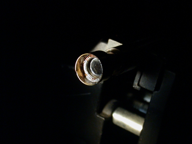
Two problems became apparent; getting light through the narrow band filters and getting the light to the subject. To get more light to the subject I turned to a very old macro photographers trick of turning a cine lens around backwards and mounting it on the video camera's 'C' mount threads (I got the lens to go on a 35 mm extension bellows but it will still work for that). This put the rear element of the cine lens to the front with no protection but not blocking the light so it is easy to light subjects with very little clearance. This lets the fiber optic light source flood the area under the lens much easier.
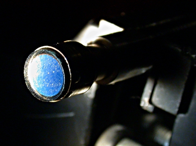
The pictures below show how the fiber was illuminated with an old A. J. Gringer Lamp and a filter holder made from nesting brass tubing that mates it to the fiber optic. In retrospect I should have made a better adapter so I could oil the fiber and the filter and improved the efficiency. The near infra red efficiency of the system was not very good. I need to try some other cameras.

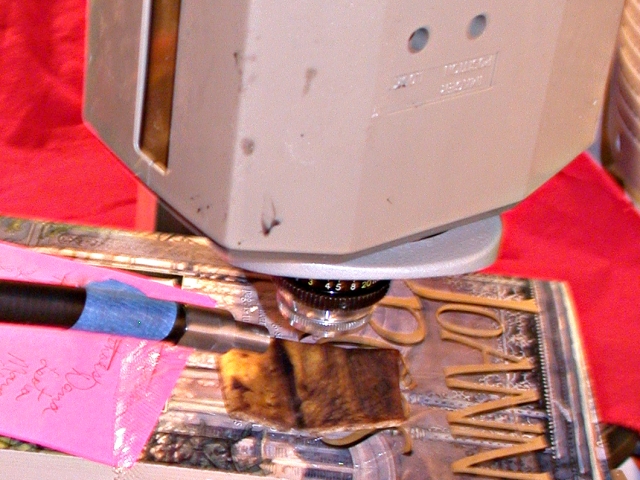
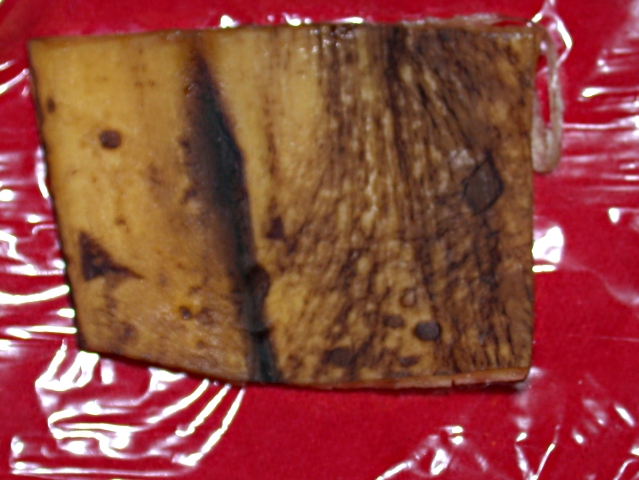
The above left image shows the fiber optic cable illuminating a banana peel and the old relic microscope lamp that puts out a full 100 watts and it adjustable down to a dim glow with the large field iris. They are handy to have around when you need lots of light or need light your can control. They go for about $20 on ebay.
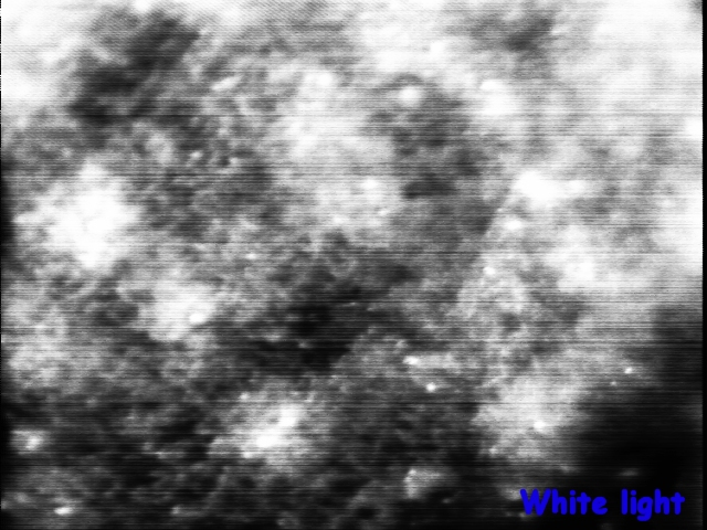
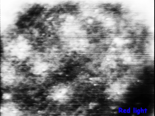
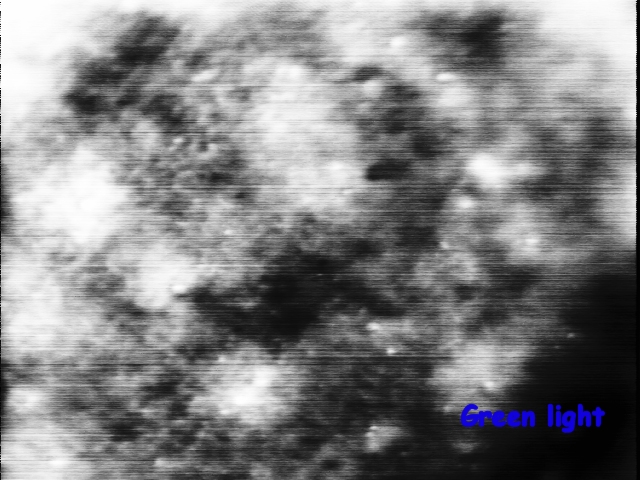
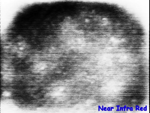
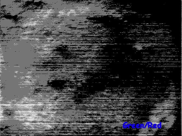
Some Results
After getting it all working and getting myself working again, I captured some images of the banana peel using red, green, near infrared and white light (image sequence below). All but the NIR image are very close to the same exposure. All the images have had their histogram equalized and the files are available on my web site and will work with ImageJ that runs on any platform and is free provided by the US government. Here are the equalized images and the results of the red image divided by the green image and the histogram equalized. I have no idea what that shows but I it is an example of what image processing can do. Go get ImageJ and download the files and play with it a while. The bitmap files are the raw data files with no processing. It is this kind of processing that we used to save 50% of the nitrogen on wheat and used to regulate weed sprayers to turn on only when a weed is in the field of view. More images will be on the site as they become available. Hopefully better than these. What I thought to be a simple project is getting quite complicated and it is not done yet.
I used a Snappy video capture device for image capture. They were made by Play that is long bankrupt but sell on ebay new in the box for 10 to 20 dollars. They get high resolution image captures from low resolution cameras using hardware and software processing. They do not capture images real-time and are annoying to focus without a monitor.
(1) Sensing Nitrogen Differences in Winter Wheat and Bermuda Grass, Marvin Stone, et. al, Better Crops, Vol. 81, 1997 #4.
Gordon Couger 11/12/02
All comments to the author Gordon Couger are welcomed.
Microscopy UK Front Page
Micscape Magazine
Article Library
WIDTH=1 © Microscopy UK or their contributors.
Published in the December 2002 edition of Micscape Magazine.Please report any Web problems or offer general comments to the Micscape Editor.
Micscape is the on-line monthly magazine of the Microscopy UK web
site at Microscopy-UK