|
by Larry Jenkins, USA |
Todays digital cameras offer an incredible level of technology and flexibility theyve revolutionized many photography applications. High-resolution cameras are still fairly expensive, however, and unless you have a Nikon Coolpix, attaching them to your microscope (both physically and optically) can provide some serious challenges. There are literally hundreds of digital models available, yet few can be mated to most good scopes with available adapters.
Notwithstanding digital advances, if you are serious about picture quality and capturing high-resolution images, its hard to improve upon film. And, if you need digital images, an inexpensive scanner provides wonderful quality conversion.
Even so, taking good quality images with the standby 35mm SLR offers other challenges: Focusing your scope accurately to ground-glass optics can be tricky, mechanical shutters cause jitter and out-of-focus images, and color balance with a tungsten or halogen source isnt always desirable. For about $20 (plus an old flash unit) the setup described below eliminates all of these problems camera focus is automatic, exposure is perfect every time without changing settings, jitter is not a factor, and color balance is daylight. The automated focus feature can be added to any 35mm setup; for auto-exposure, youll need a dedicated overhead light port, i.e., topside illumination or a camera adapter with an auxiliary viewfinder. Project illustrations are included below, following the narrative.
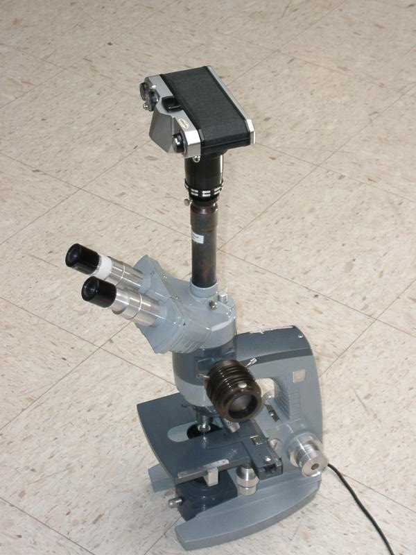
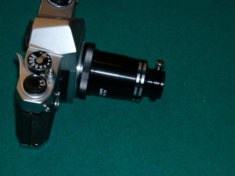
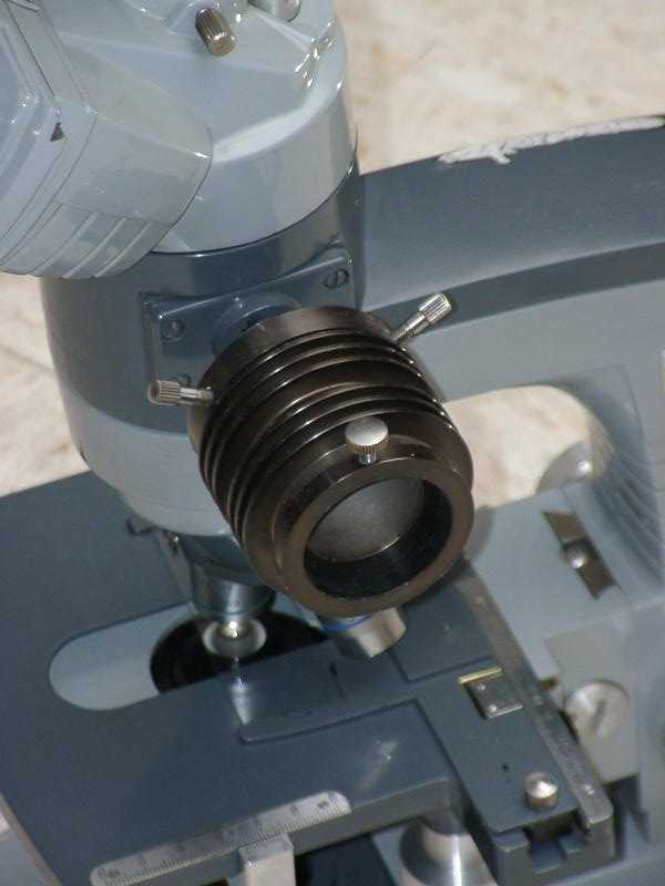
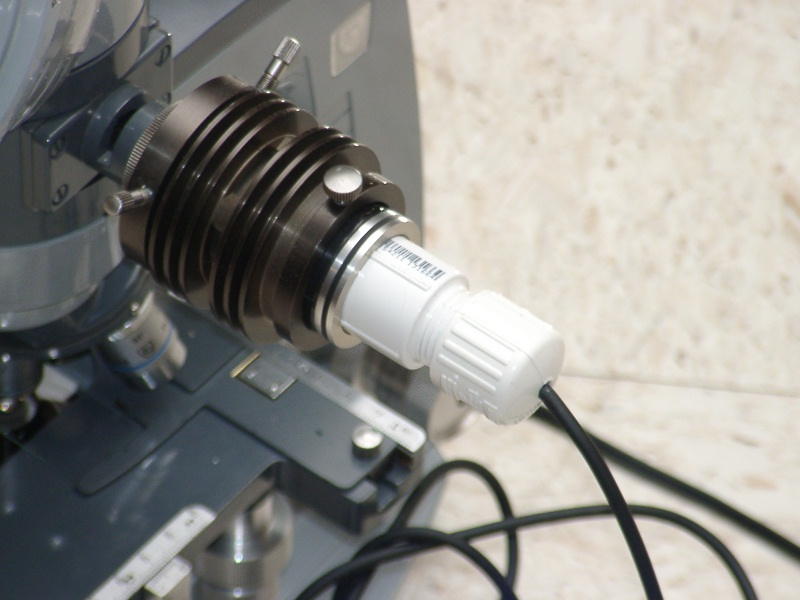
My starting equipment includes an A/O series 10 trinocular microscope, ca. 1960s, with both over and under illumination Objectives are plan achro, with resolution down to 1/3 micron using 100x oil. The overhead light port is used to mount a flash sensor if you dont have a dedicated overhead light port, theres a no-cost manual alternative that Ill describe later. I use an old Pentax Spotmatic SLR coupled to the microscope with an inexpensive T2 adapter, still commonly available. Obviously, your equipment may be different, but the principles should apply to other scopes and camera systems.
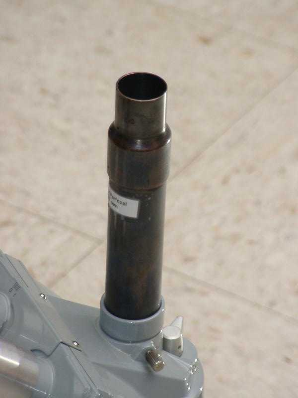
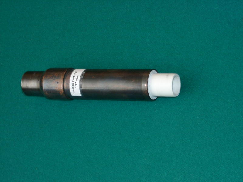
First, regarding focus: Ive found that focusing an image in an SLR viewfinder is not a reliable technique a ground-glass projection doesnt permit sensitive focus control, so you cant usually see a precise picture of the image that will be recorded. However, if the image that is projected to the cameras film plane is always parfocal with the binocular eyepieces, then theres no need to focus to the camera at all! Fortunately, there is a fixed scope-port to film-plane distance at which ALL objectives will provide a parfocal film image with the microscopes binocular eyepieces on my microscope, that is the distance at which my LOWEST power objective yields a parfocal image. In other words, all you need is the right length tube between your microscope port and your camera adapter. Chances are, your microscope manufacturer cant supply the right length tube, because different cameras and adapters have different dimensions youll have to make your own tube. To get a good approximation of the correct tube length, mount a slide and focus your eyepieces to it using your lowest power objective with the T2 adapter on your camera, and a spare eyepiece inserted into the adapter, look down into the camera port through the camera viewfinder. Move the camera up and down over the port until the viewfinder focus looks best. It helps to attach a string to the camera to gauge the right distance, or have a friend take a measurement as you focus with the camera. My optimum length is 137mm, for example, whereas A/O made a 123mm extension tube.
To make the camera extension tube, Ive used a piece of one inch copper pipe with a 1" x ¾ " reducing fitting on top (see picture) grind out or machine the fitting to accommodate the eyepiece (mine are common 23 mm), and sandpaper the outside of the fitting and the bottom of the pipe to provide a loose fit for the camera adapter and snug fit into the microscope port. Cut the copper pipe so that the assembly is the correct measured length when the pipe is inserted about 75% into the reducing fitting you might need a little wiggle room in either direction. To fine-tune the length, I marked the pipe at the bottom of the reducing fitting, then added some additional marks at 1mm increments above and below the original mark. Using the marks as a guide, I exposed a roll of film with shots at 0.5mm length increments (stick with the lowest power objective, and focus to the oculars only), then soldered the pipe to the fitting at the length that provided perfect focus. I added a short extension of ½" schedule 40 PVC pipe inside the bottom of the copper pipe, machined to fit into my microscope port, and blackened the copper and interior of the PVC. Be careful to seat all parts firmly during the adjustment process, i.e., get it right before soldering.
With the finished extension tube, you can ignore camera focus entirely using any objective lens, your camera will record exactly what you see at the microscopes binocular eyepieces.
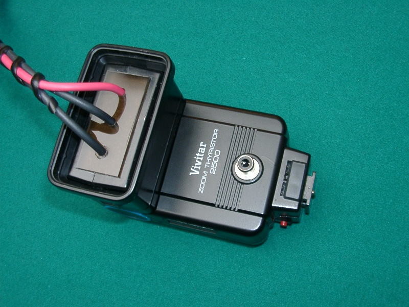
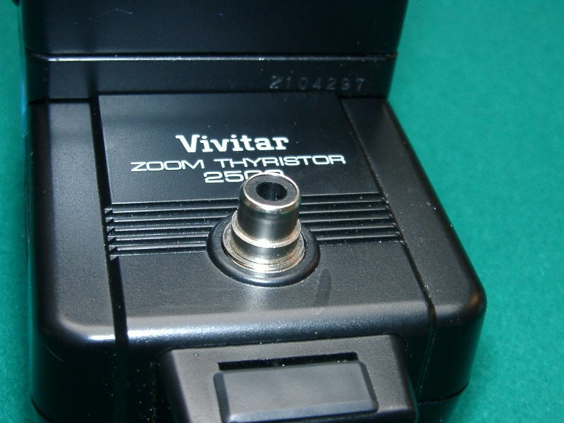
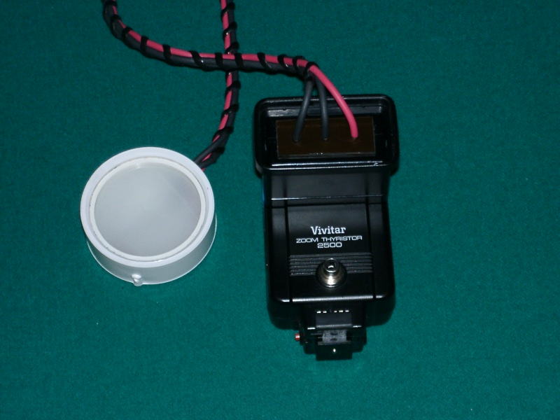
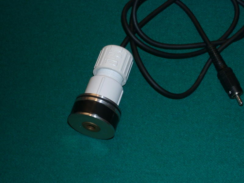
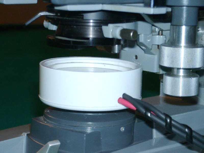
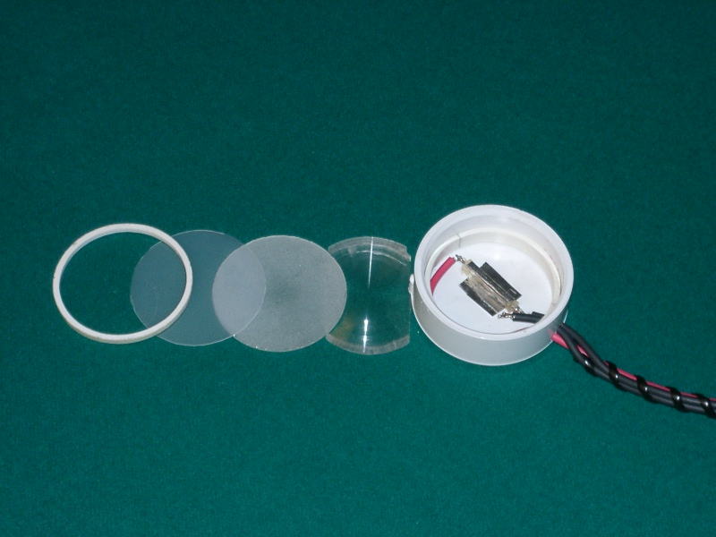
The remaining issues, i.e., jitter, exposure and color balance, are addressed by modifying a common flash unit to serve as a light source. I adapted a 20-year-old Vivitar 2500 Thyristor flash taken from my camera bag it hadnt been used for many years. Current available models are illustrated at www.vivitar.com. The flash tube is removed from the flash gun and mounted underneath the microscope condenser, using a 2" white PVC pipe cap to package the tube, a diffuser and a ground-glass disc similarly, the flash units sensor is removed and remounted in the overhead light port, so it can see the amount of light passing through the objectives. Pictures are taken using the cameras "bulb" setting, and the flash is manually triggered while the shutter is open. The thyristor-controlled flash uses feedback from its sensor to quench the flash tube, generating a longer- or shorter-duration discharge to provide more or less light output. Higher-power objective lenses are smaller, therefore require a great deal more light than low-power lenses, so automated exposure control is a truly convenient feature to include, if you have a light port available above your objectives. If you do not, however, other approaches are available: Your flash should generate enough light for proper exposure with a single discharge, using your highest power objective (mine does with ASA 400 film) for lower power objectives, you can insert a neutral density filter over the flash to moderate light output. Alternatively, you can use multiple flashes to properly expose high-magnification images.
Construction details will vary depending upon your available equipment, but hopefully the following comments and attached pictures will offer suggestions:
With these modifications in place, your camera system truly becomes an extension of the microscope. There are no camera adjustments necessary to record a perfect exposure with every shot.USE CAUTION! Photoflash units store a potentially lethal charge, typically 3000 volts and higher. They also use special capacitors that are designed to release energy as quickly as possible. Be certain your flash unit is fully discharged before digging inside! Otherwise, youll risk a nasty burn and a quick trip across the room. If theres any uncertainty, remove the batteries and let the unit sit a few hours. (Also see Micscape safety footnote). The flashtube, its reflector and diffuser have been removed from the flash unit and replaced with a small plexiglass rectangle, cut to fit properly. For extension wires to the new flash housing, use heavily insulated wire test-lead cable is fine. Drill the plexiglass to pass through the extension wires, and secure the wires internally using clamp-on sleeves and/or epoxy. All connections should be fully enclosed to eliminate any risk of inadvertent contact during use. As a final precaution, do not use an AC adapter to power your modified flash batteries work fine, and are safest. Glue the flashtube into the center of the 2" PVC cap, elevated slightly if your tube doesnt have small rubber mounting rings attached at the ends for this purpose, use a couple of small plastics chips cut from the reflector. Avoid applying glue directly to the flashtube if at all possible; if you must, do so only at the ends any foreign matter in contact with the tube adjacent to the discharge will burn and blacken the tube. Glue a narrow strip of the reflector elevated slightly above the tube, shiny side downward, to block direct view of the tube from the top. Insert a small piece of aluminum foil under the flashtube to protect the PVC double-sided tape will hold it down. Glue the wires around the edge of the cap to serve as strain relief. Cut a narrow slice of 2" PVC pipe (or several) to use as a spacer for mounting the diffuser, ground glass and plastic cover, and to hold the assembly in place. The ground glass is cut from ordinary window pane, using light pressure with a hole saw in a slurry of 120 grit silicon carbide abrasive the surfaces are ground by rotating two pieces against each other in the slurry. The top plastic disc is cut from a coffee-can cover, and the original diffuser from the flash unit is trimmed to fit inside the PVC cap. If you can find a suitable piece of ground glass that already fits, use it. After final assembly and testing of the remote flash housing, secure the top retaining ring using glue or small screws from the outside. The sensor diode from the flash unit is removed and repackaged into a holder so that it can be inserted into your overhead light port. Ive mounted a phono jack at the original location of the sensor, and use shielded phono cable to connect the sensor back into the flash unit. If there is a small capacitor soldered to the sensor, remove and relocate it along with the sensor. The diode only works in one direction, so be sure to note which wire attaches to each side of the diode before cutting the wires. Fabricate a holder that fits into your light port, glue the sensor in place and secure the wires from strain. The sensor must always have a clear view of the lens at the end of the light port the sensor is calibrated by changing the size of the opening into the light port, so start with a fairly large opening, i.e., a quarter inch diameter or larger. If necessary, calibrate the sensor by narrowing the hole through which it sees the light port: The unit is calibrated when it just achieves its most powerful discharge, viewing a medium density slide image at highest magnification. With that size hole, the discharge then should be quenched properly when lower-power objectives are used. The flash generates a heavy "thunk" sound at full power, versus a lighter "click" when it is being quenched. Finally, test your setup with different film speeds the ASA rating which will produce the best exposure depends on your flash units maximum power output.
Project Illustrations:
Click on the thumbnails for a larger view: (Full-size photos are 40-50 kbytes.)
 |
|
 |
|
 |
|
  |
|
  |
|
  |
|
  |
|
  |
|
 |
|
Typical Results:
The following pictures illustrate the focus and exposure results obtained using the modifications described.
Subject matter is a pathology slide viewed at 20x and 100x (oil) using 10x widefield oculars.
Film is ASA800 Fuji colorprint, standard processing, scanned at 300 dpi.
Full size photos are about 200 kbytes,
to permit digital enlargement.
 |
|
 |
|
Questions or comments may be forwarded
to: L. Jenkins.
Project Notes:1. The Vivitar Thyristor Zoom 2500 modified for this application has a guide number of 80 (ISO100 /ft) in its normal zoom position. The unit has manual, blue (f/4), and red (f/2) operating modes the blue operating mode is used exclusively, and provides calibrated operation when the sensor diode is exposed to the overhead light port through a ¼" hole. Vivitars current model 2800 appears to resemble the 2500 closely in its specifications; it does not incorporate zoom features, but they are not needed. A flash with a guide number of 80 or higher is recommended for use, as the overhead illumination port effectively halves the amount of light that would otherwise reach the camera or ocular lenses. With the set-up described, ASA800 film provided best exposure results, although ASA400 was also satisfactory.
2. A small PVC ring glued to the underside of the remote flash package holds the flash firmly in place over the A/O scopes built-in illuminator.
3. 55mm camera filters fit nicely into the remote flash package; in particular, with a cut-out linear polarizing filter disc inserted into the camera-adapter eyepiece, a 55mm lp filter over the remote flash package can be turned conveniently when imaging with polarized light.LJ
Micscape
safety notice:
The flashgun
modifications are given by the author in good faith for those skilled in
electrical construction and who are familiar with the potential dangers
and precautions required in modifying electronic flashguns. If in any doubt
about correct procedures do not attempt to modify a flashgun. People with
a heart condition may be particularly at risk from an electric shock if
the procedures and precautions aren't adhered to.
Disclaimer: No responsibility is accepted by the author, On.View Ltd who host Microscopy-UK / Micscape, the site administrators or other site contributors for any harm to persons or property incurred by following this project.
For those not
wishing to modify a flashgun but are interested in the use of flash with
a microsope, see for example the Micscape article by James Evarts, 'Adapting
a flash gun for photomicrography'.
Microscopy UK Front Page
Micscape Magazine
Article Library
Published in the February 2002 edition of Micscape Magazine. Please report any Web problems or offer general comments to the Micscape Editor,
via the contact on current Micscape Index.Micscape is the on-line monthly magazine of the Microscopy UK web
site at Microscopy-UK
WIDTH=1