 |
| Collimating Low Power Stereo
Optics Tackling a difficult problem by employing fundamental principles By Paul James (UK) |
This article is concerned principally with the collimation of a low power stereo microscope which had decollimated optics. The actual methodology and the attendant principles involved in collimating its optics, are universally adaptably to similar 'scopes, which hopefully might give the reader some confidence to tackle a similar job.
The problem
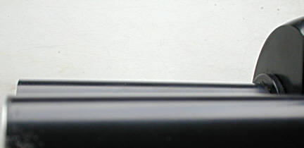
This particular low power stereo 'scope had its right hand eyepiece tube permanently misaligned by about 2-3 degrees in relation to the other, and consequently the imagery was also misaligned. It had obviously been knocked at some time and so was acquired cheaply with the aim of correcting the problem. The damage was slight but a previous owner had tried to adjust both internal prism positions in an attempt to cure the problem, and whilst failing also removed any hope for me to find undisturbed optics in the unaffected left hand optical assembly from which I could have recalibrated the disturbed right hand prism assembly.
|
You can see the discrepancy above.
Finding a foundation to work from
It was fairly obvious at the start that I had to work from first principles and try to think of a way of correcting the misalignment of the prism assemblies in both sides. The only way to do this I thought would be to locate the central optical axis and work from that. Fortunately the main objective and magnification changer were pristine and undisturbed.
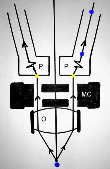 |
The diagram above is basic but shows the fundamental principles and layout of this 'scope. The light path is shown for one ray bundle emanating from dead centre which passes in a collimated 'scope eventually through to the centre of each eyetube. The only parts of the instrument where we can be fairly sure to locate the optical axis is below the objective, and also at the top and bottom of the unstrained eyetube. The blue spots indicate these points. Note the magnification changer has its clear aperture set for simplicity, and also note the pivot point, where the prism block assembly and eyetube in tandem are designed to pivot horizontally so that the interocular spacing can be adjusted for the eyes. This point must be mechanically and optically as one, otherwise misalignment would occur every time the interocular spacing was adjusted. Thus collimation is assured for all settings of the eyepiece 'spacing'. Note that the prisms light's pathway has been ignored for the sake of diagrammatic simplicity.
Note also that this 'scope does not have parallel eyepiece tubes, but converging ones. The more common type using parallel tubes usually has 2 prisms each side.
The Solution
Since the instrument has a shared single objective, I reasoned that a central point at the objective's working distance would issue a light beam to each prism assembly which if collimated accurately, would yield in each eyepiece a centrally located image of the field's centre.
 |
To find the central point of the field of view of the objective was important to determine accurately, so I devised a simple method of achieving this. It seemed logical to me that if a target were placed below the objective which consisted entirely of a multitude of concentric circles, then any deviation from the optical axis would be easily seen through the eyepiece. But first I had to locate this target mechanically and accurately below the objective to establish the target's concentricity.
The 'target'
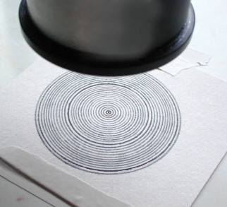
A piece of white card was marked with concentric circles, making sure that the field at lowest power would be more than covered by their span and the alignment cylinder described below. Also important too is that the centre should be precisely defined, and that the first set of circles around it were small so as to be visible within the field at the highest power. I 'drew' the circles using a spinning platform, but of course a compass would have easily produced them.
Mechanical placement of target beneath the objective
Simply aligning the target beneath the objective by viewing through the eyepiece cannot be relied on when the 'scope is decollimated of course, so I had to devise a mechanically accurate method.
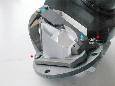
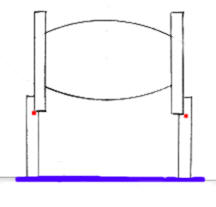 |
This was achieved by making a cylinder that would accurately fit over the end of the objective, and of a length which placed the objective exactly at its working distance. The internal rebate made sure that the cylinder was at right angles to the optical axis of the objective. The objective was carefully lowered onto the target, which was adjusted so that the nearest circle to the cylinder visible on the outside would reveal the accuracy of its concentricity. This simple method assures that the face of the objective is also parallel to the stage on which the target is placed. When satisfied with its concentricity, the target was taped down. The first part of the location of the optical axis was completed, so that the target centre was also at the optical centre and would appear so in the eyepiece when perfectly collimated.
Prism alignments etc..
 |
The next job, that of realigning the prism of the undamaged left hand side was carried out. The eyepiece tube and cover were removed to reveal the prism in its cell. Note the screws that hold the prism firmly in the cell, and the screws that hold the cell itself. Both sets of screws can be adjusted giving more than enough scope for alignment. The centre of the target was brought into the centre of the field by adjusting this prism. I knew then that by observing the rings through the eyepiece I would instantly recognise any discrepancy between the concentric circle nearest the field boundary. So by tweaking the position of the prism on that side I soon brought the field boundary and circles to concentricity. A final confirmation of collimation was to observe these concentric circles at each magnification level. Theoretically the centre of the target should be dead centre at each level of amplification. Thus the left hand side was now collimated. So far so good.
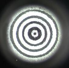 |
Here's the view of the target down the eyetube. Putting in the eyepiece to view the field boundary's concentricity is the final and most revealing test.
The difficult part....the right hand misaligned eyepiece tube
Much thought was put into the next operation, because I had two options. The first was to mechanically realign the righthand eyepiece tube's seating.....an altogether risky job which may have ended up distorting all of the prism bed on both sides. I decided against this because I knew from experience that a mistake here would compound the problem and I'd end up with far more work. The second option, that of packing by any suitable means the base of the eyepiece tube to restore its original position was chosen, though it did involve much experimentation and of course time. By using thin metal shim washers and very thin hard plastic where necessary, I eventually brought the right hand eyepiece tube into alignment with the left hand tube. Then the job of aligning its prism was attended to, so the centre of the concentric circle also fell precisely into the field leaving the right hand image merging precisely over the left...............with the reward of collimated optics and superb viewing.
The very last operation was to set the two eye tubes to interocular distance and check that both images merged naturally and comfortably with the eyes. Any subtle tweaking of the right hand prism could be left to this stage.
Concluding Points
It is essential in recollimation work that a 'foundation' be established, and in this case all I could use was the fact that the objective's mechanical centre would be the optical axis and of course the centre of the undisturbed left eyetube. Between these extremes lay the prism, which in this case was disturbed and had to be reset.
But a perfectly collimated binocular optic should not only provide a comfortable and coherent image for both eyes, it should also provide identical field positions in relation to the subject. Thus the lateral accuracy of the eyepieces and lack of any 'yaw' is to be taken into account too.
It is a simple fact that though the image itself might 'appear' collimated because the imagery seems perfectly merged or fused together, the field boundaries might not be 'fused' or merged into one. The cause is either the prism misalignment, tube displacement or yaw OR a combination of these!! Perfectly aligned optics yield concentric field boundaries and imagery at all settings of the magnification changer.
The final arbiter in being satisfied with the recollimation is a subjective one :-
When the eyes are raised to look forward in front of the 'scope, there should be no sensation of readjustment of the eyes, save only that they will have to adjust divergence or adjust focus slightly. Collimated parallel eyetube 'scopes should allow the eyes to rapidly observe the image and then a distant scene through a window with consummate ease.
| All comments welcome to the author Paul James |
Microscopy
UK Front Page
Micscape
Magazine
Article
Library
Please report any Web problems or offer general comments to the Micscape Editor.
Micscape is the on-line monthly magazine of the Microscopy
UK web
site at Microscopy-UK