"Taking Microscopes from the Stone Age with
High Wattage LEDs"
Robert Pavlis, Girard, Kansas, USA
Shortly after joining the faculty of the University of the Virgin Islands in 1969, I met Professor Paul Burkholder, a rather well known faculty member there who had a large collection of microscopes. The two that immediately caught my eye were his Wild M20 and his Wild M40. It was obvious just by looking at them that both of these instruments were of absolutely the highest quality.
When I saw the M40 in use I quickly realised that it was not only an unusual looking instrument, but its inverted design made it possible to obtain truly amazing views of marine microorganisms. The students in his microbiology classes would often concentrate living organisms in sea water samples by filtration, and then observe them with this instrument. The Wild M40's peculiar phase contrast system was ideal, because organisms could be observed without squeezing them between a cover slip and a slide.
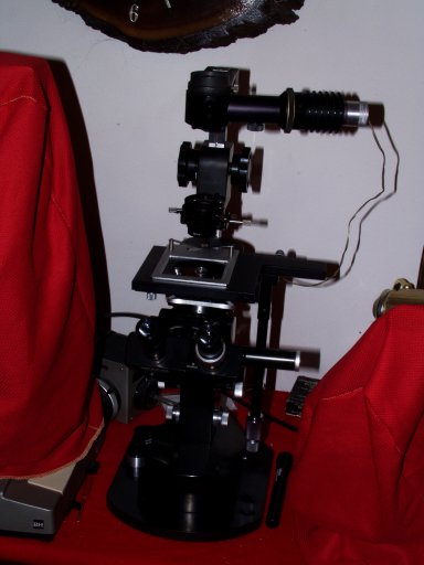 A few months ago I found, rather by accident, a Wild M40 for sale in an ebay auction. The seller said in the description that it was in very good condition, but missing a power supply and oculars. I placed a bid on and, amazingly I got it! A few days later the instrument arrived. Considering this instrument is around 40 years old, it was in amazingly good conditionin fact it looked almost like a completely new instrument. Although the seller had advertised that it included the rather difficult to obtain special bulb, the one with it had a separated filament.
The Wild M40 in the Virgin Islands had had two or three different slide carriers, this one came with only one, one with a large opening about 75 mm square for holding various containers. So far I have not had need for any other ones. Parts for this instrument seem nearly impossible to obtain, but if I find I need any other type, I can make them easily using the milling machine. This wonderful microscope came with 3 objectives, a 4X, a 10X phase, and a 20x phase corrected for 1 mm thick glass. The phase insert for the 10X objective was in the condenser, but the 20X one was missing.
The lack of the 20X phase ring insert was a serious matter. I attempted to locate one from scientific supply organisations and from Internet sources and found none. However, it was obvious to me that this was a VERY easy thing to make with a lathe. I took a piece of aluminium stock and made one in a few minutes. Instead of using a glass disk with a painted ring I suspended a metal disk in my phase insert. I decided I had better paint it black inside to prevent stay light. I discovered that it worked as well as the commercial ones.
Although I was certain I could obtain a proper 6 volt power supply, and I had a source for the special (somewhat expensive) Osram bulbs used by this instrument, it seemed to me more sensible to replace the incandescent bulb system with an high wattage light emitting diode one.
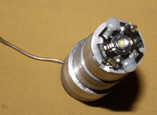
 I obtained a small "emergency" LED light from one of our local department stores. I machined a little collar to enable me to insert it into the lamp housing. Although this worked quite well, it was not quite bright enough. I learned that much brighter LEDs are available, 1 watt, 3 watt, and 5 watt. The 3 watt seemed most sensible, so I ordered some from an Internet source in Edmonton, Alberta. The ones mounted on a star shaped piece of aluminium seemed ideal for my purpose. They are sold as "star LEDs".
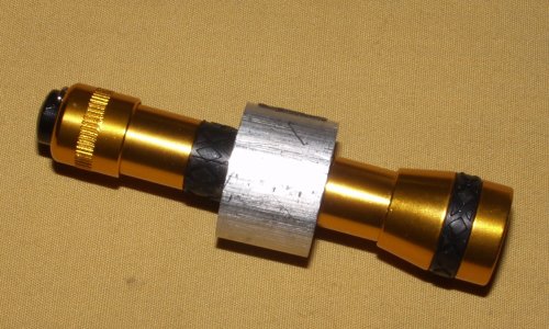
When the LEDs arrived, I used a lathe, milling machine, and band saw to construct a special holder for these. (See below)
For a power supply I obtained a small plastic holder for four AA Cells with a switch. I placed a 2.8 ohm resistor in series with it, and connected it to the leads. The LED gave off a truly brilliant white light! I inserted it into the holder on the M40 and tried out. It more than met my expectations. I had planned to add a dimmer circuit, but this is not necessary, as the brightness is about ideal for all powers I have available. The four rechargeable AA cells provide about 5 volts. I could increase the brightness somewhat by using a slightly smaller resistor, but that seems unnecessary.
The field is perfectly illuminated with all objectives between 4X and 40X. The colour of the light is much closer to daylight than incandescent. In reality it provides much better illumination than the system that Wild supplied in the first place. The design of this particular illuminator is particularly suitable for upgrading from incandescent bulbs to LEDs. I have no intension to look for a 6 volt power supply or to purchase the standard incandescent bulb because this is MUCH better.
The 20X phase ring insert that I constructed provides beautiful dark field illumination with the 4X objective.
Some day soon I plan to make another illuminator identical to this one, except with a green star LED. This should provide better contrast with the phase system.
"Why Incandescent Bulbs are Poor for Microscopes"
Microscope designs have steadily evolved since the first microscopes were built about 400 years ago. Throughout the centuries microscope illumination has always been a severe problemin fact until very recently it has been such a severe problem that designers generally have had to settle for the "least bad" design rather than the best!
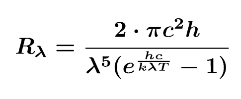
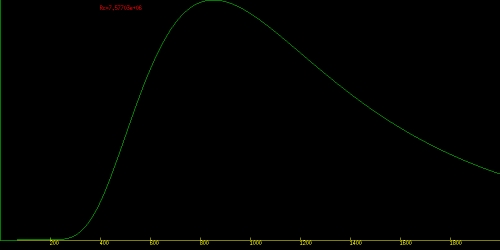
Shortly after their invention, incandescent light bulbs based illumination systems were developed. However, they were still a very poor solution to the problems. Incandescent light bulbs operate by using resistance heating to raise the temperatures of filaments to temperatures high enough so that they radiate visible light. In the early twentieth century a formula was developed that predicts the wavelength distribution emitted by a black body at a given temperature:
I wrote a simple C program written for the X system to display the radiation curve for black bodies. Click here to obtain this.
The design of incandescent light bulbs has one critical flaw, namely that there do not exist any substances that can be heated to sufficient temperatures to produce a suitable wavelength distribution before they melt or their vapour pressures become so high that the filament simply vaporises!
Tungsten has the highest melting point of any metal. It melts at about 3800 K. The graph below shows the wavelength range produced by a black body heated to this temperature. Note that the wavelength of maximum radiation is around 800 nm, at the approximate boundary between infrared and red. Blue and green wavelengths are quite deficient.
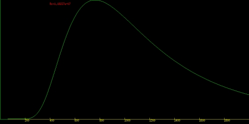
In reality, however, tungsten filament lamps cannot operate at the melting point of tungsten, the vapour pressure of this metal is so high at this temperature that the filament would instantly vaporise! Tungsten filament lamps are normally operated at temperatures of around 3000 to 3200 K to prevent this. Incandescent light bulbs can operate at this temperature for weeks at a time without failure.
A few decades ago a new design for tungsten filament lamps appeared on the scene. These lamps had a small quartz envelope and contained small quantities of iodine. As tungsten metal is lost from the filament it reacts with the iodine, forming volatile tungsten iodide. When this somewhat compound contacts the hot filament it decomposes and redeposits the tungsten on the filament. This permits these lamps to operate at substantially higher temperatures, at temperatures near 3400still substantially below the melting point of tungsten. The curve for 3400 blackbody radiation is shown below:
The graph below shows the blackbody radiation curve at 3400K. Notice that the wavelength distribution is noticeably poorer than at 3800Kthe short wavelength visible wavelengths are weaker, and a larger portion of the energy is in the infrared.
The reality is that incandescent lamps are really much better near infrared sources than visible light sources!
Tungsten filament lamps have yet another difficulty, the standard way to dim them is to reduce their temperature, this shifts the radiation even deeper into the near infrared.
Arc lamps are a rather old invention. They have problems too. Perhaps their biggest disadvantage is that gases emit line spectra rather than continuous ones unless the lamps are run at extremely high pressure. Running them at high temperature and pressure creates an explosion hazard, and it is very difficult to manufacture such lamps. Consequently they are very expensive.
Fluorescent lamps have been in use for many decades. Microscopes require a small intense source of visible light. Fluorescent lamps produce light that is far to diffuse for most microscope applications.
Light Emitting Diodes, commonly called LEDs, were developed relatively recently. These solid state devices can produce very intense light. Infrared and red LEDs have been available for many years. Green ones appeared on the scene a bit later. A much more recent development is the blue LED. Blue LEDs can be combined with phosphors to make white LEDs. Because humans have tri chromic vision with three primary colours-red, green and blue, white light can also be achieved by combining a red, a green, and a blue LED.
Recent improvements in LEDs make them much brighter than earlier models. They cost much more than standard incandescent bulbs, but much less than the special dedicated incandescent bulbs used in most microscopes.
"Fabrication Instructions for Wild M40 LED illuminator"
It is fairly simple make a part like this. Ideally one should have a lathe, a milling machine, and a metal band saw to do this as well as a good micrometer. The lathe, however, is absolutely essential.
The following materials are needed:
- 1. Solid aluminium or brass rod for the body of the new illuminator.
- 2. An appropriate star LED. (3 watt one seem most practical.)
- 3. 1 metre (or so) of two strand insulated wire.
- 4. 2 3mm Nylon screws (for mounting the LED)
- 5. Materials for building a power supply. Exactly what is needed depends on personal preference.
Aluminium alloys vary dramatically in their machinability. Some alloys tend to stick to cutting tools badly, these are not suitable for machining parts like this. Other aluminium alloys are amongst the easiest materials to machine. Many brass alloys are extremely suitable for machining. Brass tend to be somewhat more expensive, however than aluminium. It is also much denser so that parts made with it tend to a bit heavy. This latter factor probably makes it so that easily machinable aluminium is the preferred material for this project.
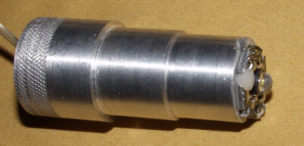 The lamp holder of the Wild M-40 microscope is 26mm in diameter. A lamp carrier must consequently be machined to slightly less than this diameter. Oddly, the inside of the Wild lamp holder is slightly smaller in diameter, so more is required than simply obtaining a 26mm diameter cylinder and attaching a LED to the end of it!
The best approach seems to be to start with a rod slightly over 30mm in diameter and machine it to a suitable shape. A simple way to do this is as follows
For the Wild M40 the best length seems to be 60mm. Cut it off to that length with a band saw. Place the rod in the lathe chuck and use a centre drill to support the rod whilst it is being machined with a live (or dead) centre. If you choose to use a dead centre be sure to lubricate it from time to time, especially with aluminium alloys. It is best to use the centre drill on both sides of the rod. Face both sides of the rod first. Then turn it down to 30 mm through its full length, turning it around in the lathe midway through the operation. Now turn it down to just under 26 mm along the 40mm portion of the rod that will fit into the lamp holder. This diameter must be cut quite accurately! Finally turn the part of the rod that will fit into the smaller diameter of the lamp holder down to about 23 or 24 mm. This is the last 20mm of the piece. This diameter is not as critical. Be sure not to leave a sharp edge where the diameter of the piece changes, otherwise it will be difficult to insert into the lamp holder socket. There should be either a 45 degree flat edge for about 1 mm, or a rounded edge with radius about 1mm.
 Now drill a hole all the way through the work piece with a drill bit that will produce a hole just large enough for the power wire to pass through it. Try not to make this hole any larger than necessary. Drill into the hole used for the live or dead centre used during the turning operation. This hole can bored either using a lathe or a drill press. To avoid drilling 60mm with a small bit one can drill half way through, and then finish the operation by drilling from the other side. All that really matters is that the finished hole is large enough all the way to hold the wires that will deliver power to the LED.
Remove the rod from the lathe or drill press. The star LEDs have grooves cut for holding 3mm screws. Place the LED on the end of the piece just machined and use it as a template to mark the points where two holes will need to be drilled to attach it with these screws.
Set the LED aside, and carefully drill two 1 cm deep holes into the piece you have machined using a special bit designed for generating holes to be used for 3mm taps. Be careful! Tap the holes with a 3mm tap. Taps this small break easily. Again be careful. When tapping aluminium it is particularly important to move the tap forward and then back out a bit instead of running it all the way in one operation.
Check that the two threaded holes are correct. Mark the top of the piece again where wires will need to come between two other points of the star along side the soldering tabs. Place the piece in a milling machine vice and cut a slot all the way across the top of the piece about 4 mm deep to hold the wires. Do not make the slot much wider than enough to hold the wires.
Remove the piece from the milling machine.
Solder the wires to the LED.
Pull the two stranded wire through the machined piece. If there be available heat transfer paste, put some on the bottom of the star LED. (This will enable the LED to run cooler.)
Bring the LED against the end of the piece and attach it with the two 3mm screws. These need to be nylon because otherwise they will short out the wires.
Slide the new lamp holder into the housing on the microscope. The mechanical work is now finished!
The next item on the agenda is to devise some sort of power supply. There really are two types of reasonable choices: An A, C, or D cell power supply, or an AC power supply. Many low voltage DC power supplies are produced today for a variety of electronic gadgets, usually they produce voltages from 4.5 to 6 volts. These work very well, but a current limiting resistor must be employed, the size of which will depend on the voltage of the power system employed and the wattage of the LED.
Electronic supply stores tend to sell special 2 and 4 cell holders. Only the 4 cell ones are suitable, because two will only provide 2.5 to 3 volts, depending on the type of cell employed. Three cells are really ideal, a dummy cell can be placed in the fourth position to provide 3.75 to 4.5 volts. Again a current limiting resistor may be needed.
"What about other Microscopes?"
These LEDs can obviously be used for a great many microscopes. The surface area of the LED emitting surface may be too small to provide proper Köhler illumination without adding a diffuser or a supplementary lens. The M-40 has a diffuser built in, as do many other microscopes. Getting the whole thing set up properly can take a bit of effort and a bit of design work.
Many tungsten filament microscope illuminators are designed so that the lamp is carried at the end of a cylindrical piece of metal that fits into a sleeve like on the Wild M40. On many of these microscopes the diameter of the metal lamp holder is around 25 mm. The star LED diameter is around 20mm, so holders can easily be machined to replace the tungsten filament bulb holding ones.
A second option would certainly be to machine a holder for a star LED that would fit into the bulb socket on the original holder.
The Wild M40 has a special diffusing lens in the illuminator. Microscopes without such a system may require placing some sort of diffuser in front of the LED to serve as the source to be imaged unto the image plane for Kohler illumination.
Some illuminators are too small in diameter to accept the star LEDs. Fortunately LEDs can be obtained in other packagings too.
The power supply with microscopes that have them internally can generally easily be modified to provide direct current by adding a diode. A proper limiting resistor, however, is also essential!
This Wild M40 now has a much better illumination system than it had when it was manufactured about 40 years ago.
I described how I built a "proto" light source to house a small LED "emergency" light. I used this to determine important parameters for the system with the star LED. It was especially useful to determine just where the LED needed to be in the illumination tube, and to determine whether or not some sort of diffuser would be necessary.
All comments to the
author
Robert
Pavlis
are welcomed.
Microscopy
UK Front Page
Micscape
Magazine
Article
Library
©
Microscopy UK or their contributors.
Published in
the February 2006 edition
of Micscape Magazine.
Please
report any Web problems or
offer general comments to the Micscape
Editor.
Micscape is
the on-line monthly magazine
of the Microscopy UK website at Microscopy-UK
©
Onview.net Ltd, Microscopy-UK, and all contributors 1995 onwards. All
rights
reserved. Main site is at www.microscopy-uk.org.uk with full mirror at www.microscopy-uk.net.