|
A home project by
|
 |
Important safety notice.
This project requires in part the wiring and assembling of mains voltage
(110-240V) components by an experienced and qualified electrician and also
requires a well ventilated enclosure. Please read important safety notice
at the article foot.
I want a cool light that is also small to get it close to the objective and fiber optics seems to be just right; but to buy a 150 watt unit is very expensive. So for starters I made a 20 watt version of the higher powered unit.
In a very short trial I liked it quite well; one of the inhabitants in a micro-pond has shown me what he really looks like, the whole image lights up very nicely using the fiber light from the top as incidental illumination.
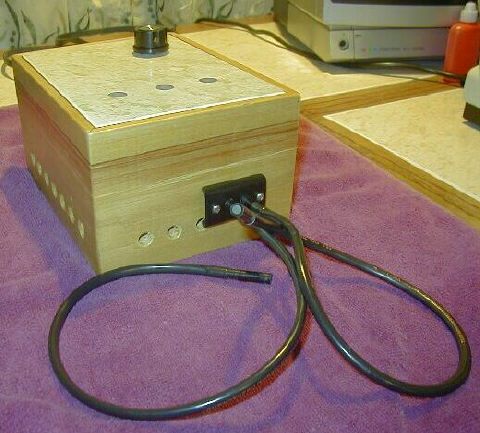
The style of the box is made a little old fashioned, more like furniture, to get away from all this clinical look, the function and technicalities shall be of modern design, but simple. The wood is piranha pine 1/2 inch thick, and the ceramic tile for the top is cut from a Spanish floor tile 3/8 inch thick. Overall the box measures 7 X 5 3/8 X 3 3/4 inches high.
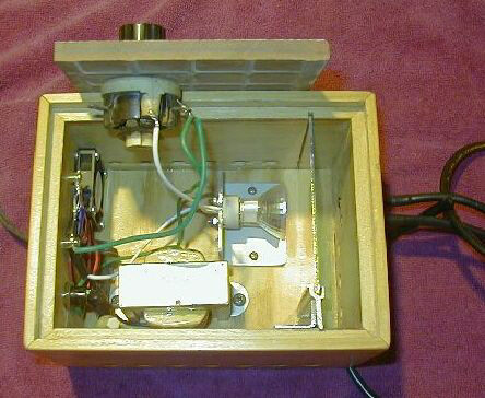
This illustrates the author's
suggested layout for an experienced electrician
to design and build a suitable
version. Take particular care with
isolating/insulating the mains
side from the low voltage side.
Loom the wires carefully to keep
them away from the hot lamp
and rheostat.
Surfing the Internet I found 18 inch long fiber optic light guides and 12 volt halogen lamps with socket and transformer, also a heat reflecting glass. This glass has another very good quality, it does not let any infra red light pass through. I only got to know about the infrared light aspect, after reading the Micscape article "Experiments with a miniature CCD camera - further notes" and all the different comments that there are from other people too. I am mostly concerned not to melt my fiber optic cable that has a plastic shield, that is why I installed the reflecting glass.
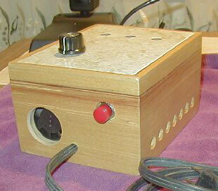
The fan is essential to keep the box cool and uses a little 12V 1.5 inch diameter fan. The fan sucks air from a 1 1/2 inch hole in the back panel and blows it over the lamp and out of all the holes at the sides and three of them at the top. I am glad I did not use a stainless steel plate for the top for this reason, but it was a lot more work to make the holes through the 3/8 inch thick tile. but that is really worth the trouble, it looks much better too. <Editor's note: a metal top/box would need careful earthing>. My neighbor Mr. Bird (an experienced electrician) was kind enough to design the power supply for the fan, and sourced the rheostat to dim the light. This has to be of a wire-wound type capable to handle the wattage of the lamp and maybe a little more to keep it from getting hot.
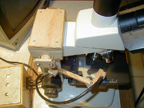
The rheostat can also turn the light off; this lets me run the fan for a while longer to cool things down, before I use the red push button on the back to switch the whole thing off. To put the light fibers close to the objective and keep them there, I have made an adjustable holder, that fits onto the microscope. It has two arms; each has 1 ball joint and 4 straight joints that only move in one direction. On the end is a holder for the fiber cable. It is made of oak and the parts are rather to small to work with power tools, except an electric drill, I cut all the parts with small hand saws.
This is a 120 volt system, in countries with 110V or 240 V mains, an experienced electrician can source the correct transformer and other parts to assemble in a suitably designed and safe enclosure. So please be careful here!!
Comments to the author Rudolf Baumueller welcomed.
Footnote: I ordered the lamp and
transformer, the glass and the fiberoptics light-guides from C and H Sales
Company, 2176 Colorado Blvd.
Pasadena, California 91107
Tel. 1-800-325-9465 Fax 626-796-4875
http://aaaim.com/cgi-local/shop991/shop.pl/page=start_shopping.htm
Important safety notice:
The project above is given as a guide by the author in good faith for those skilled in both mains voltage and low voltage electrical construction or to offer to a skilled qualified electrician to source the correct components and build. Under no circumstances should an unskilled person attempt this project. Mains voltage devices can kill if not assembled properly with the correct components and must be properly fused and earthed (the latter especially if an external metal casing is used). Also if not properly ventilated it could be a fire hazard as well as an electrical hazard.
Disclaimer: No responsibility is accepted by the author, On.View Ltd who host Mic-UK / Micscape, the site administrators or other site contributors for any harm to persons or property incurred by following this project.
Additional note: An experienced electrician will be able to design a simple safe circuit with suitable components with the above article as a guide.
Microscopy
UK Front Page
Micscape
Magazine
Article
Library
© Microscopy UK or their contributors.
Please report any Web problems or
offer general comments to the Micscape
Editor,
via the contact on current Micscape
Index.
Micscape is the on-line monthly magazine
of the Microscopy UK web
site at Microscopy-UK