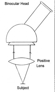
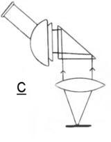
Have you felt that the low power end of the magnification spectrum is not very well catered for? I'm not referring to stereo low-power 'scopes, just the low power end of the compound microscope. A magnification of say x20 is still high for many subjects, even if we use a low power eyepiece the field is limited. So I had a simple idea of using a standard compound microscope's binocular head together with a relatively long focus positive lens, such as a 50mm camera lens to effectively produce a compound image of low power.The basic arrangement in principle looks like this:-
 |
The notion of making a binocular low power stereo microscope is not new, but making one which is in effect a very low power binocular compound microscope ( vlpbcm ! ) is one I could not resist investigating. The combination of the binocular head and camera lens yield images, which though lacking in true stereoscopic perspectives, allows some spacial perception with fatigue free use and quality imagery, and can be considered as being a Rolls Royce binocular loupe !
Camera lenses
I opted to use camera/enlarging lenses because I already have a number of older 35mm types not being used. The quality of the images leaves little to be desired from these lenses, despite their being corrected for different use, and they come with iris and screw or baynet mounts making adaptation use all the easier. The fact that the full aperture of the lens isn't realised is not a problem, and in practice means that the iris is only noticeably effective when closed down somewhat to start with. The essential point is that they are capable of forming decent contrasty images which can be scrutinised with the eyepieces in binocular head.
Lens reversal ( This is not an essential procedure )
The images can benefit by reversing the lens so that the inner face normally pointing towards the film plane is actually facing the subject or specimen.* This is fortunate because the wide angle lenses need to be closer to the specimen and so the rear element which is usually flush with the barrel allows some working distance. Enlarging lenses are also ideal as they are designed to do what we want here, namely magnifying a small plane into a larger one.
Reversing a camera lens actually helps with mounting, because all we need is a filter thread to support it. In my case I was lucky enough to possess 4 lenses of 28mm, 35mm 50mm and 58m all with a 39mm thread !
* This is not vital, but if the lens is mounted with its bayonet in the normal way, advantage can be taken of the in-built focusing mechanism. Filter-thread mounted lenses make this focussing mechanism redundant, so it is necessary to decide whether the internal focussing mechanism is vital for your particular needs. You might feel that the convenience of using the lenses' own focusing mechanism outweighs any image degradation caused by using the lens in this way? The difference between the images produced by the two methods of supporting the lens will vary from lens to lens, but I have found very little difference, and certainly not enough to cause concern. The simplest support is the 42mm thread which many older lenses possess, and using a thin extension ring embedded in the 'box' face as described below makes for the easiest method of supporting all of these lenses.
Focal length/magnification
Using a standard 50mm camera lens, within close proximity to the aperture of the bino' head, and x10 eyepieces I obtained a magnification of approximately x12, which is about the power I was hoping to achieve. A 35mm lens gives correspondingly higher powers ie about x20, and a 28mm even higher still, and a 75mm enlarging lens I have produces about x8 power.
Increasing the distance between a given lens and the eyepiece also increases the magnifying power, and so we can make a poor man's zoom ! Though to accomplish this requires more engineering skills in a DIY instrument.
To zoom or not to zoom ?
If you have a 35-70mm SLR zoom which is redundant, then you have the answer to your quest for a range of power ................ It couldn't be simpler!! The drawback is that the working distance at the longer focal lengths is quite something! So if you'd like to incorporate a zoom lens into the plan then I'm afraid that your stand or assembly will have to cater for a wide ranging working distance ? Don't let me put you off the idea, try it and see.
Personalising the 'scope
It sounds good so far, so are there any problems? Not really if we are to use the set-up in the vertical position as shown above, because the image is inverted, and this does not present any real problems when examining subjects on horizontal surfaces since they can be easily turned to suit the observer.
However, I also wanted to examine Hydra in a water cell orientated in the vertical, so ideally the optical train would have to be horizontal, but unfortunately as I've mentioned before, the images are inverted. To get around this problem we can use an inverting lens, but this increases the overall length of the assembly, and so to retain simplicity and compactness the use of a right angled prism ( or mirror ) was decided upon .
A 45 degree prism can be used to achieve an upright image, though we have to accept that some binocular heads reverse the image. ie. mirror imaged, though some will present a 'normal' erect image.
Like most things in life there are compromises, and the choice of which of the configurations above to make depends on materials to hand and personal preferences. The use of a prism or aluminised plane mirror is essential, and since contrast in the image is paramount, the less glass involved in the optical train the better, and if we use achromatic lenses with good anti-reflection coatings such as camera lenses then there is every reason, if they are properly aligned, to expect and enjoy good images.
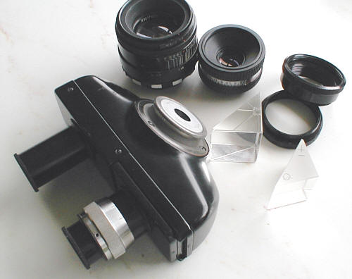 |
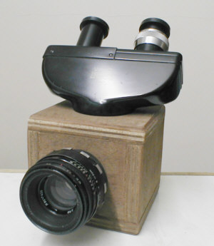
"The Essential Ingredients" |
Thoughts about design of stand and assembly of components
Fortunately the camera lenses which have threads/bayonets couple conveniently to their respective extension rings, allowing some variation of magnification. So basically what is required is a 'box' in which to house the prism accurately, hold the lens/extension ring(s) and bino'head on top, and some form of attachment between the 'box' and a stand.
If possible I'd want the instrument to be able to move from the horizontal to the vertical axis. Fortunately, as luck would have it the spare binocular head I have is of the type which is capable of 360° rotation, and this facility is useful for my simple design :-
 |
 |
 |
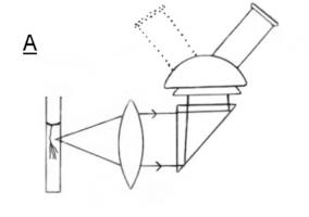
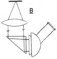
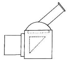
A...... Horizontal setting, in which the bino head can be swivelled to invert the image if need be.
B...... Inverted microscope setting which may prove useful ?
C ..... Is the normal down hand setting
A universal low power microscope design??
The 'Box'
The 'box' is the DIY bit and heart of the unit and holds all the pieces together, and is aptly named since it is a hollow cube firmly supporting the internal prism or mirror and the two ring supports each for the lens and bino-head :-
 |
Whatever material is used to construct the support or 'box' it is probably better to think of it as an optical support and stand all in one as it were. It is important to realise from the start that the prism or mirror need to be close to both the lens and prism or mirror so that the 'tube length' is kept as short as possible, otherwise too much magnification will result. Of course anyone can incorporate a sliding tube arrangment to allow the main lens to move away from the prism or mirror in order to increase magnification if they so wish, but this might make the whole unit cumbersome and unbalanced? Best I think to keep it simple and well balanced, and the arrangement shown above fulfills these two parameters with ease.
I wanted to make a prototype first to try the idea out, so I used ply for all the parts of the 'box', and decided to use an aluminised mirror cut down from an internal mirror from an old photocopier.
I used a thin 42mm extension ring to support the main lens, a Zenith Helios 55mm f2 for trials. The ring was simply screwed directly into the hole produced by a forstener bit on a pillar drill. The hole for the bino-head was cut in the same manner and two machine thread screws had their points removed so allowing them to 'nip' the inner ring to prevent movement when screwed through the edge of the top ply piece.
The mirror was glued to a 45° block wedge to the bottom of the box and aligned square facing the back of the lens.
TIP
The simplest method of aligning optics is as follows :-
Fit the camera lens first so as to be square with front face of box. Fit the mirror accurately making sure that its centre is at the same level as the lens axis. Taking a piece of ply a little larger than required for the bino-head top piece, drill the hole to receive bino-head and then after mounting the latter in it securely, rest this top piece assembly on the box roughly in position, and close the camera iris right down. Look through the bino-head's eyepieces and adjust the top piece until the vignetted appearance of the field of view/image appears central. Then mark the top piece position and trim and fix.
This will have aligned the binohead accurately over the optical axis, saving accurate measurements, time and effort, and ultimately does the job well.
|
The prototype allows experimentation and the discovery of any flaws either in the design of the 'scope or in its use. |
Conclusions
In practice this DIY low power compound microscope works extremely well, providing sparkling imagery and contrast. I use a pair of B&L x 15 achromatic oculars and the image is sharp to the edges, especially at f8-11. Lacking a true stereoscopic performance is not noticed unduly, and the stability and ease of use plus simplicity, is a bonus. Plenty of light is required to illuminate the specimens, but this is a simple point and shouldn't put off anyone interested in constructing this modular 'scope.
I recommend those interested, that they satisfy themselves first by making a crude and simple mockup from their optical components, to see if the images are satisfactory and of a useful magnification. It pays to find out as much as possible from trying various combinations and orientations of the optics before any decisions about mounting them are taken. Using an existing bino-head from your 'scope will demonstrate the effectiveness of this design.
|
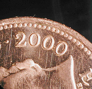
Image of 1p coin, (approximately x10, Olympus C-830L). |
PRO'S
1) Very simple design not requiring ultra precision alignments.
2) Excellent views.
3) Adaptable to various observing configurations.
4) Box mounting provides stability and adaptability.
5) Can be made easily in an afternoon.
CON'S
1) Images not truely stereoscopic, but some spacial perception is noticed.
2) Requires bino-head, which can be relatively expensive, but they can be found
in used condition for a reasonable sum.