|
A Demonstration of the Use of Quarter & Whole Wave Plates to |
The crystals that are photographed under a polarizing microscope are referred to as anisotropic because they split light rays into two secondary rays (a phenomenon called birefringence). These rays travel at different speeds and in different directions. When the rays recombine after leaving the crystal, they are out of phase, and interference occurs. Some colours of the white spectrum are cancelled out, leaving the crystals with a resulting hue. Compensators are optical devices which slow down one of the rays even more, and therefore increase the phase difference between the two rays. This results in the crystals having different colours than they did before the introduction of the compensator. Photomicrographers can make use of this phenomenon to change the colourization of a particular image to suit their fancy.
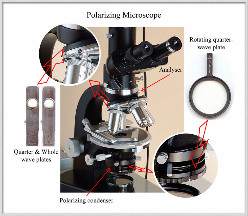
The image below shows my polarizing microscope, (a 1960's vintage Leitz SM-Pol), with the compensators discussed in the article.
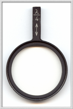
One type of compensator is round in shape, and fits into a slot in the polarizing condenser immediately above the polarizing filter. It can be rotated through approximately 90 degrees. The other compensator type is rectangular in shape, and fits into a slot in the objective carrier immediately above the objective.
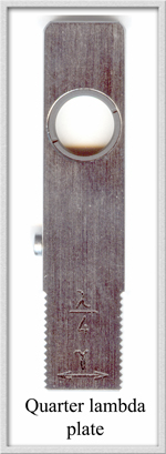
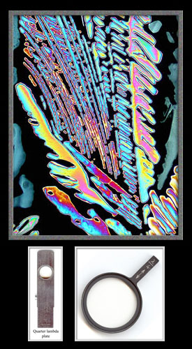
Quarter-Wave Plate or Quarter-Lambda Plate
This compensator comes in the two forms shown above, but both perform the same task. The optical material chosen has an index of refraction and thickness that result in a retardation of one of the rays by a quarter of a wavelength (about 140 nanometres). Historically, mica was used in the manufacture, and this type of compensator was often called a mica plate or glimmer plate. (Today, all plates are manufactured from specially engineered materials.)
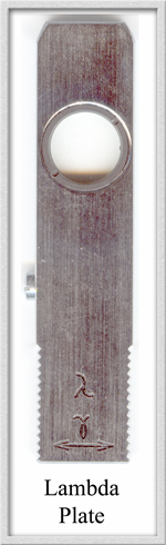
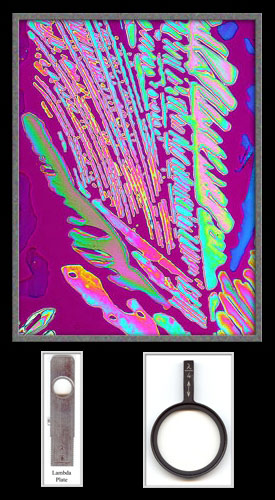
Whole-Wave Plate or Lambda Plate
This type of compensator is usually supplied in the form shown above. It slows down one of the rays four times as much as the plates discussed above. The retardation this time is about 550 nanometres. The compensator was formerly called a gypsum plate, sensitive tint plate,or first-order red plate.
The Comparison Setup
An evaporation specimen of the amino acid Beta-Alanine was placed on the microscope stage and the rotational position fixed. A Nikon Coolpix 4500 digital camera was used to record the images. Except for the first photomicrograph, the polarizing condenser was adjusted to give a black background (extinction position). For the remaining images, (in addition to the polarizing condenser), a compensator, or compensators were positioned to alter the colouration. The details are shown beneath each image. All photomicrographs were subjected to exactly the same post-processing in Adobe Photoshop Elements 2.
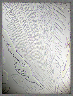
Part A
The beta-alanine specimen viewed with ordinary transmitted light is shown on the left. On the right is the same view with crossed polars and no compensators.
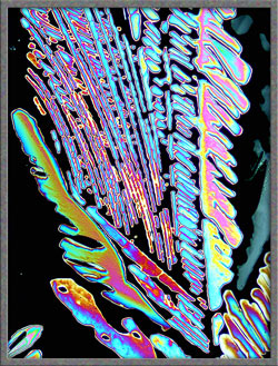
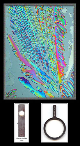
Part B
A single quarter-wave plate or whole-wave plate was positioned in the slot above the objective.
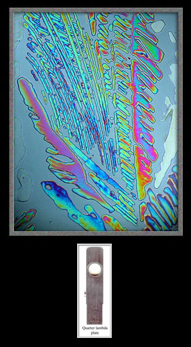
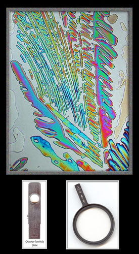
Part C
A single rotating quarter-wave plate was placed in the slot of the condenser and rotated.

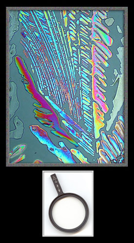
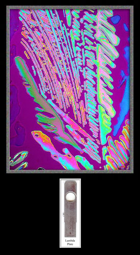
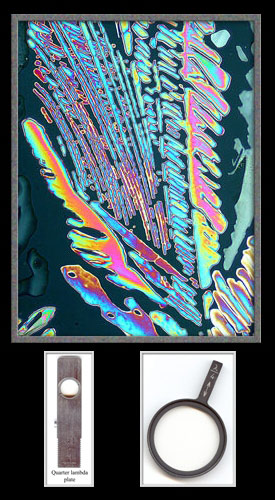
Part D
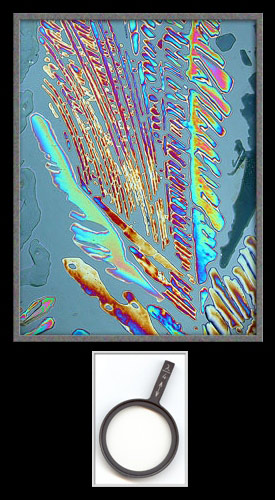
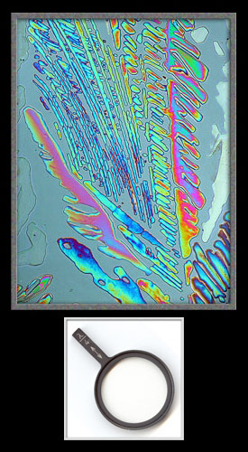
A quarter-wave plate was inserted into the slot above the objective and a second rotating quarter-wave plate was positioned in the slot of the condenser. The lower compensator was rotated. (Note: this configuration produces circularly or elliptically polarized light depending upon the rotation angle.)
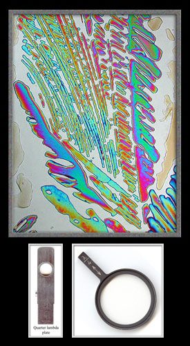
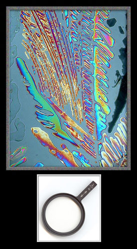
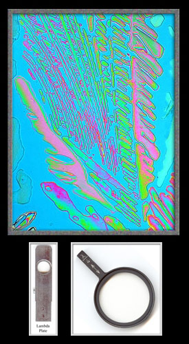
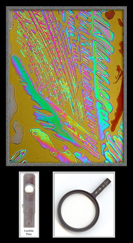
Part E
A whole-wave plate was inserted into the slot above the objective and a rotating quarter-wave plate was positioned in the slot of the condenser. The lower compensator was rotated.
I hope that the photographs presented in this article give a hint of the many image enhancement possibilities resulting from the use of compensators in polarized light photomicrography.
All comments to the author Brian Johnston are welcomed.
Published in the January 2005
edition of Micscape.
Please report any
Web problems or offer general comments to the
Micscape
Editor.
Micscape is the on-line
monthly magazine of the Microscopy UK web
site at
Microscopy-UK
© Onview.net Ltd, Microscopy-UK, and all contributors 1995 onwards. All rights reserved. Main site is at www.microscopy-uk.org.uk with full mirror at www.microscopy-uk.net .