|
|
A Gallery of Tetramethyldiaminodiphenylmethane Photomicrographs (using
a variety of illumination techniques) |
|
|
A Gallery of Tetramethyldiaminodiphenylmethane Photomicrographs (using
a variety of illumination techniques) |
As you can see from the title, organic
(carbon based) chemical names can be tongue-twisters! The name of
this compound is pronounced as
tetra-methyl-di-amino-di-phenyl-methane. It is commonly used as a
universal reagent in thin layer chromatography to identify drugs.
During the production of many dyes, the compound acts as an
intermediate. Historically, it was used in analytical chemistry
for the identification of lead.
Tetramethyldiaminodiphenylmethane
is a solid consisting of pale yellow leaflets or plates with a melting
point of about 90 degrees Celsius. This very low melting
temperature permits a melt specimen to be prepared by heating a small
quantity between a microscope slide and cover-glass. Note that
the MSDS safety document for this compound states:
Clear
evidence of carcinogenic properties in animals. Anticipated to be a
human carcinogen. May cause reproductive damage. Harmful if inhaled,
swallowed or absorbed through skin. Irritant.
May cause methemoglobinemia, which
is characterized by chocolate-brown colored blood, headache, weakness,
dizziness, breath shortness, cyanosis (bluish skin due to deficient
oxygenation of blood), rapid heart rate, unconsciousness and possible
death. Animal inhalation studies have reported the development of
tumors. Effects may be delayed. Laboratory experiments have resulted in
mutagenic effects.
The three melt specimens used in
this article were prepared in the fume-hood of my lab while I was still
teaching chemistry. (I am now retired.)
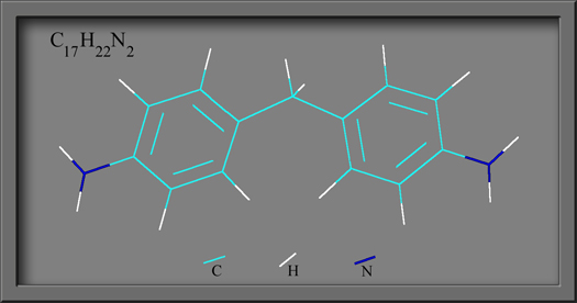
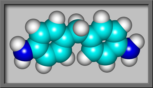
Tetramethyldiaminodiphenylmethanes
structural formula and molecular shape are shown below. Both
images were produced using HyperChem
Pro software. Notice that the molecule has two benzene
rings bonded to a central carbon. A nitrogen-based amino group is
attached to each benzene ring.
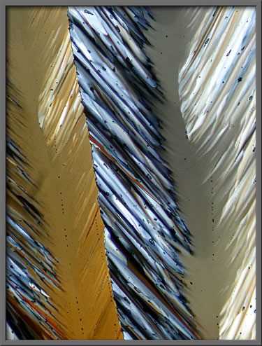
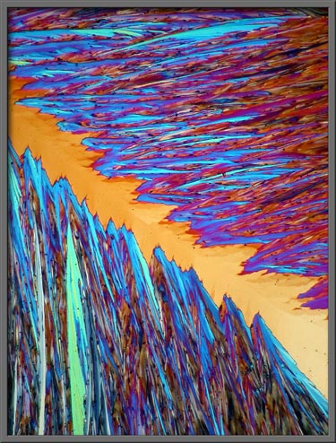
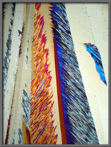
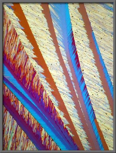
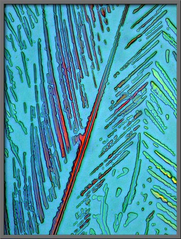
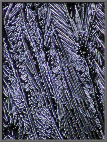
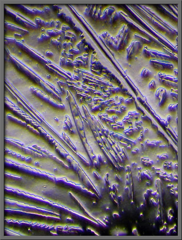
The first image in the article
shows the distinctive feather-shaped forms that often occur in melt
specimens of the compound. (Unless otherwise stated, polarized
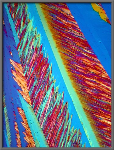
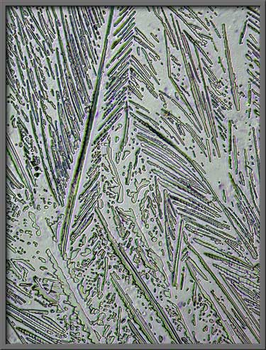
light is used for illumination.) Two higher magnification images
of these feathery areas are shown below.
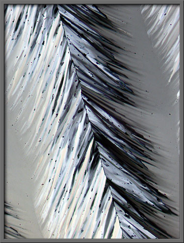
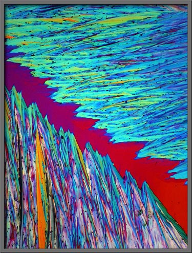
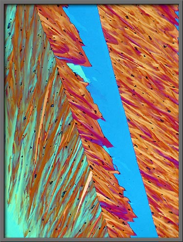
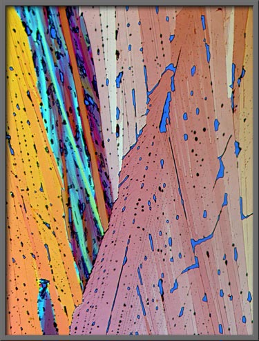
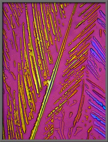
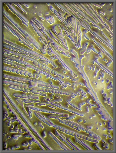
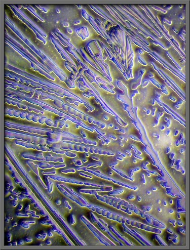
Compensators can be used to alter
the colouration of a particular field. In the two images
following, lambda and lambda/4 plates were used, and the lambda/4 plate
was rotated to produce the colour difference.
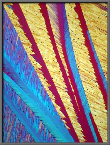
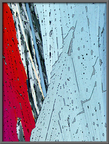
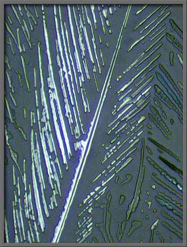
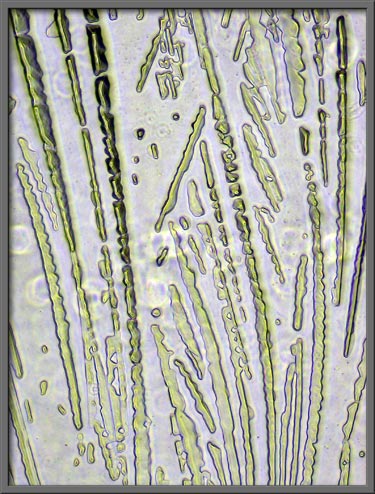
If
pressure is applied to one area of the cover-glass as the melt cools,
the resulting crystal layer will be thinner. Under polarized
light, this often results in images that are shades of gray rather than
brilliantly coloured.
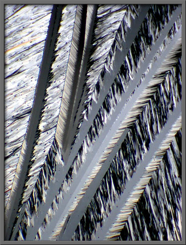
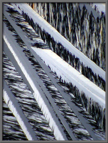
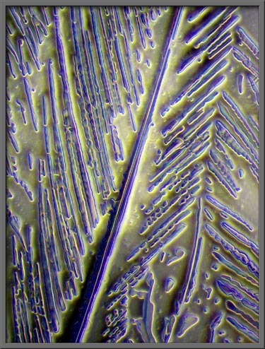
The image on the left, below,
utilized two lambda/4 compensators, while the one on the right utilized
lambda/4 and lambda compensators.
Below is a higher magnification
photomicrograph of an area shown in the right hand image above.
The use of compensators can
completely change the appearance of a particular field.
You may have to take a second look
before you realize that all three images below are of exactly the same
field!
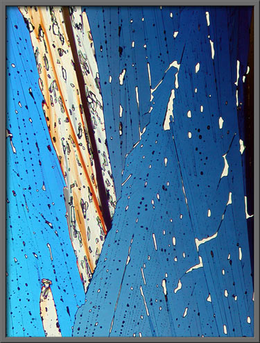
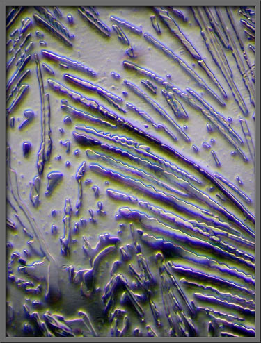
The first three images use
polarized light and compensators. The fourth image was produced
by using a phase-contrast condenser instead of a polarizing one.
However, instead of fitting a phase-contrast objective, a normal
objective was used. Doing this sometimes results in images with a
distinctive three-dimensional appearance.
A similar field, (at lower
magnification), using a dark-ground condenser resulted in the following
image.
Here again, a phase-contrast
condenser coupled with a non-phase objective were utilized to form the
images.
As mentioned before, by choosing
the right annular stop of the phase-contrast condenser, and the right
non-phase objective, very 3-D-like images can be produced.
The final two images show one
particular field. Both use the same non-phase objective. A
different annular stop was used in the second image. Although
both photomicrographs show three-dimensional characteristics, these
seem to be more enhanced in the second image.
Photomicrographic
Equipment
The images in the article were
photographed using a Nikon Coolpix 4500 camera attached to a Leitz
SM-Pol polarizing microscope. Images were produced using several
illumination techniques: dark-ground, phase contrast and polarized
light. Crossed polars were used in all polarized light
images. Compensators, ( lambda and lambda/4 plates ), were
utilized to alter the appearance in some cases. A 2.5x, 6.3x, 16x
or 25x flat-field objective formed the original image and a 10x
Periplan eyepiece projected the image to the camera lens.
All
comments to the author Brian
Johnston are welcomed.
Published in the
January 2007 edition of Micscape.
Please report any Web problems or
offer general comments to the Micscape
Editor.
Micscape is the on-line monthly magazine
of the Microscopy UK web
site at Microscopy-UK
© Onview.net Ltd, Microscopy-UK, and all contributors 1995 onwards. All rights reserved. Main site is at www.microscopy-uk.org.uk with full mirror at www.microscopy-uk.net .
