Ordinarily we can see transparent objects because light is deviated by its being both refracted and reflected when it meets a refractive index change. Thus when we sit down to dine we have no difficulty locating the crystal water glasses that are sitting in front of us. When we observe objects by transmitted light using microscopes the light is refracted and reflected the same way that it is when we are dining and drinking water from the crystal glasses. However, because microscope objectives generally take in a fairly large cone of light, much of the refracted and reflected light also reaches our eyes causing clear objects to appear indistinct. Furthermore, the wider the cone of light taken in by the microscope the more indistinct things appear.
Because low power objectives typically have a rather small numerical aperture, they take in a rather narrow cone of light, so objects that differ by index of refraction are typically much more visible than with large numerical aperture lenses. For that reason many people feel that phase contrast is not necessary for low power objectives at all.
However almost everyone who has ever used low power phase objectives realises that, even for very low power objectives, phase contrast is still a very good thing!
Unfortunately microscope manufacturers make very few phase objectives below 10x. They are so uncommon, in fact, that I decided to write this article about them for this issue of Micscape.
If one examines dozens of microscope turret phase condensers one is very unlikely to find even one with a phase annulus for any objectives below 10X!!! (I have worked with microscopes for many years and have NEVER seen such a condenser!)
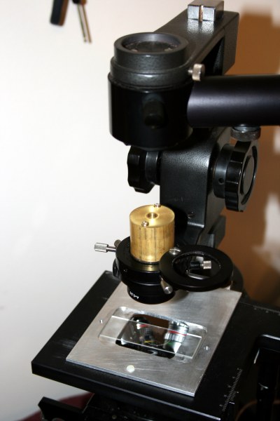
When I found a 4X phase objective for sale at an eBay auction a while back I placed a bid on it because I thought it would be a great addition to the Wild M40 microscope that I had refitted. This instrument is described in the July 2006 edition of Micscape. To me the Wild M40 is about the ideal instrument for observing living specimens, so if I have an opportunity to upgrade it in any way I tend to do so. Because this instrument does not use a phase ring turret condenser there is never a problem with phase rings sizes, because ones can easily be produced in any size as described in the above Micscape reference.
To my surprise, I had the winning bid. When the Nikon 4x phase objective arrived I put it into the objective turrert of the Wild M40 and machined a phase ring for it similar to the ones described in the article referenced above. Because of the low numerical aperture of this objective I discovered I needed to make an extraordinarily small phase ring. I attempted to make a tiny metal disk only about 3.0 mm in diameter with the lathe. I turned some bar stock down to this size, but the disks were so tiny that I kept losing them when I cut off the sections! Thus I turned to paint. I put a black dot of paint on a cover slip instead. This takes a bit of patience. Getting small dots the right diameter takes a lot of trials to get one just the right size!
When I had the phase ring finished I tried it out and found the results very very disappointingas the phase effect was only in the central part of the image.
The result was a bit less disappointing when I carefully adjusted the condenser and light source. However, no matter how I adjusted it, I could not get a satisfactory image over the whole field.
After analysing the problem a while I realised that the problem was that the low power objective covers a much wider image area. This makes vertical positioning of the phase rings much more critical than for other phase contrast objectives. The solution occurred to me when I woke up one morning at 2:00. I got out of bed to make the measurements.
I removed the phase ring entirely. I placed a slide with pond water on the stage and brought the organisms on the field into focus. I carefully focused and centred the condenser so I could see the edge of the field stop of the light source when it was stopped down. I adjusted the field stop so it was just at the edge of the field. When I moved an index card into the light path from the front just below the light source the field darkened from the bottom. When I moved it into the light path just above the condenser it darkened from above! When I moved it into the light path between about 15 mm and 20 mm above the condenser plane the field darkened evenly. The phase ring needed to be here! (Not near the condenser lens as with the Wild 10X and higher objectives.)
I tried to go back to sleep again, but I was too excited. I got up a bit before 4:00 and searched my supply of brass stock. I found a round bar of 360 brass that was perfect. I measured off a piece and cut it off with the band saw. I carefully faced the ends of the brass piece and then carefully turned down the end of the piece that would fit into the Wild condenser so that part of the piece above the turned section would be 18 mm long. Even at 4:00 in the morning this must be done with great precision. I aimed for a diameter of 29.97 mm. After working with it a few minutes I took a micrometer and measured the diameter. It was exactly 29.97mm! I took it to the microscope. It was a perfect fit. (Machinists know that removing metal is a one way proposition. Once you cut something too small you can not put more metal back on!)
Now it was time to bore out the brass bar. The goal was to hollow it out to about 15 millimetres except to on the side opposite the turned end. There it would be only the correct size for the outside of the phase ring.
I drilled to within three millimetres of the end of the bar with a 10mm bit, and then bored the hole to 16mm diameter leaving a flat surface 3mm thick at the bottom. Several years ago I obtained at an auction sale a set of drill bits in the so called "number and letter gauge" sizes. The larger sizes are represented by letters. Z is the largest, A much smaller. The size below A is #1, and after that increasing numbers indicate a smaller drill size. The set obtained at the auction has all sizes from Z down to #60. This is a truly bizarre way to denote drill bit sizes! The diameters of these drill bits are all irrational numbers in any measurement system, and there is no formula to determine their diameters. Hence one needs a special table to know the size of any given bit!
I knew that the phase ring needed to be larger than the #30 drill (3.264mm), so I drilled the end to this size first. I put it into the microscope, focused everything, and checked to be sure. It was, as I had determined, quite a bit too small. I went to the next larger size, #29 (3.454mm). I enlarged the hole to this size. It was still too small. So It was back to the shop for the next larger size #28 (3.569mm). I enlarged the hole with this, and checked again. It was getting closer, but still too small. Now it was time for the #27 drill bit (3.658mm). This was getting close! Now I had a problem. It was still too small but maybe a #26 (3.734mm) would be too large. I, however, put the #26 in the chuck and enlarged the hole to this size. With a bit of concern I took it back to the microscope and checked. It was perfect. If I had drilled it too large there would have been a serious problem, because they do not make "undrill bits" to make smaller holes!
Now it was time to make a central stop. I took six large round cover slips and placed a drop of enamel at the centre of each. Often the drops are too large, too small, or elliptical instead of round. The diameter of a useable drop must be near 3.3 millimetres.
When I determined that I had produced a cover slip with a central enamel drop that was the right size, I attached the cover slip to the top of the brass piece I had machined by using three tiny drops of epoxy cement. I put some cheek cells between a cover slip, centred my new phase ring system, and examined them. The image was absolutely perfect with extremely strong contrast.
Then I sat down to a breakfast at about the time everyone else in the community was doing the same thing!
I quickly learned that having the thin glass cover slip with the painted dot on it exposed to hazards was a bad idea! I picked up the phase ring assembly and managed to break the cover slip. I made another, and attached it. In order to avoid breaking it this time, I decided it needed to have a cover. I machined a cover from a very short piece of bar stock and bored it out so that the cover would fit over the cover slip with the enamel drop. I drilled two holes in the body of the phase ring body and then tapped it for 3mm threads. Unfortunately during the tapping operation tap oil got under the cover slip and ruined still another cover slip occulting disk!
Instead of using cover slips for this replacement, I took a carbide pencil and cut up a microscope slide into several pieces and painted the dots the same way I had with the cover slips. Once again I made six. As it turned out when the paint was dry only one was the right diameter. I attached it to the top of the holder. I centred it while looking through the phase telescope, and applied 4 tiny drops of epoxy cement to each corner of the glass piece. I centred the disk again and waited for the cement to cure, and then applied the top again.
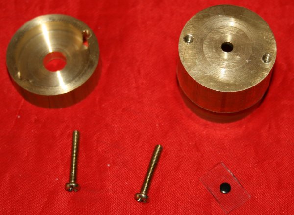
The image below shows the parts before assembly:
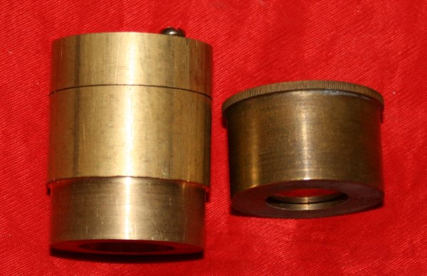
An image of the new phase ring assembly is shown below. The left image shows the one for the 4X Nikon phase objective. The one to the right is one for a 20X Olympus phase objective for comparison to a normal phase ring assembly for the Wild M40.
An addition to this instrument that was supposed to be simple turned out to be a much larger project than anticipated. It would probably be extremely difficult to design phase rings for a low power phase objective mounted on most normal microscopes, because the phase ring placement is so critical and tends to fall inside the condenser assembly where manufacturers of phase condensers place the phase rings!!!
Since the article in June 2006 I have modified the assortment of objectives on the Wild M40. The present set seems almost ideal:
The instrument has had also had two more embellishments. I have added an aluminium cover to place on the stage to reduce dust falling onto the objectives, and I have gotten one of the "Buck puck" power regulators for the LED illuminator. If one purchase the alternating current model of these devices, one can continue to use the original Wild power supplies. The deluxe model has a trim adjustment and has leads that are run to a potentiometer to adjust light intensity.
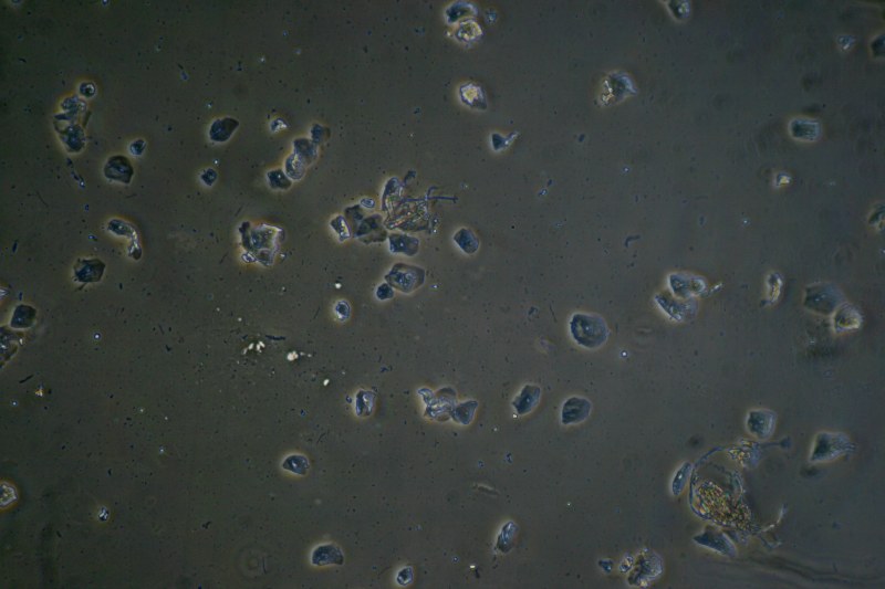
The image below shows cheek cells taken using a Canon digital single lens reflex camera attached to this Wild M40 microscope using eyepiece projection.
All comments to the author Robert Pavlis are welcomed.
Microscopy UK Front Page
Micscape Magazine
Article Library
Please report any Web problems or offer general comments to the Micscape Editor .
Micscape is the on-line monthly magazine of the Microscopy UK website at Microscopy-UK