The Novitiate’s Odyssey.
Episode Three: A few words on creation.
by G. Joseph Wilhelm, Florida Keys, USA
“Tubby or not tubby; that is the question, pilgrim.” (John Wayne reciting Shakespeare, Hamlet 3/1 - Key West)
Greetings once again from the land where the average fellow has more fishing rods than pairs of pants and if you put twenty of the local girls in one room you have almost a full set of teeth. By the time you read this our holiday season will have come and gone. Our annual late October bacchanalian debacle of debauchery is over (the Key West version of Mardi Gras called “Fantasy Fest”) where morality and good judgment take the back seat with Johnnie Walker and Anhauser Busch. The 50,000 people who parade our streets in body paint sans most of their habiliments are gone and life is back to as normal as it will ever get here. Halloween, Thanksgiving, my wife’s birthday, Christmas and New Year’s Day closely followed this celebrious activity. Whew! Being full on into the winter season here the temperature has plummeted (It got so cold last night I had to turn off the air conditioner), the snowbirds have arrived and I now find some time to resume my pen to paper efforts.
Update: There has been a noticeable course of recurrent personal illumination, every week or so, that I have learned all there is to know of microscopy. The inevitable subsequent revelation that I have had inadequate tutelage leads me to suspicion the generally accepted adage that “You can’t teach a new dog old tricks.” Also, my inability to effectively control the eBay addiction has led to the acquisition of a legion of microscopically relevant accessories as well as a dramatic increase in my concourse of cameras with associated devices/adaptors allowing interface with my microscopes. Accordingly reinforced, I venture now to illumine the pursuance of a binocular microscope suitably compatible with my idiosyncratic tendencies and the procurement of same, which will be based upon the sound principles of déjà vu, reincarnation and the fact that inanimate objects speak to me.
Allow me to explain (Please be advised to reread paragraph five of episode one and re-apply any of the aforementioned descriptors), but first turn off the Twilight Zone theme music, it’s in your head, I can hear it.
As far back as my memory serves me I have always found the world around me quite fascinating in general, but there were instances that evoked a reaction far above the norm of juvenile interest and curiosity. These occurrences were quite commonplace and summoned forth a considerable depth of emotion. It wasn’t until later in life I began to notice a pattern and was able to identify the feeling. As a young lad, visiting the Cincinnati Art Museum, I peered into one of the late 19th century restored room displays and was immediately transfixed by the roll top desk there. This desk elicited strong feelings of familiarity, comfort, warmth and what I can only describe as a tactile sensation of homesickness. The same scenario was oft repeated with different objects as the initiating stimulus and varying types and degrees of sentiments, sometimes including anxiety. The familiarity was always present. These occurrences became so routine as to be without noteworthy consequence to me. I assumed everyone experienced them.
Similar above related instances have taken place throughout my life and seem to be associated with an era between the early 1880s and late 1940s. This, along with the conviction that I couldn’t have reached my current state of comfortable maladjustment in a single lifetime gives forth the presumption that I may have been here before and while I cannot associate it with an individual I can certainly place it in a particular timeframe. This also seems to explain my affinity with objects from this period that compromise 99% of my collections. How this relates to a microscope selection will be revealed shortly.
The Spencer stereoscope restoration related in the previous episode has rewarded me with some magnificently wondrous hours of entertainment and satisfaction. This has prepared me for the next step into serious microscopically enabled observation.
I now was desirous of a quality binocular instrument as modern and consistent with my collections as possible which meant I would be looking at those stands I considered as a “bridge” between my vintage scopes and the harsh angular design of the modern instruments of the 20th century’s later years. The “top four” manufacturers with the following requirements were considered:
It had to be black. This may seem an irrational parameter at first, but irrational fits me very well. All of the grey /gray (which is really correct?) and white microscopes fall outside of my collection era comfort zone.
It should have the 160mm tube length because most of the (affordable) after market objectives were within this specification.
The design had to be aesthetically pleasing as per the above-cited era.
Parts/accessories as used items should be readily available as upgrades.
The binocular head needed to be on a rotating 360 deg dovetail mount so as to view from behind or in front of the arm.
I basically used eBay to research the availability, price etc. of the Leitz/Leica, Olympus, Nikon and Zeiss stands that fit my paramount specifications. Leitz almost had me with the early Dialux, Laborlux and the Ortholux as depicted in Gregor and Normand Overney’s excellent article, but the 170mm tube length design, while still able to accept the 160mm objectives dictated that the correct match up of objective/eyepiece could be a problem. The Olympus BH stands were close but black ones and parts seemed scarce and even more so for the early Nikons.
And then, browsing the Molecular Expressions microscope museum, I was stricken,
“But soft, what light through yonder window breaks? It is the east and the GFL65 8-56 4 is the sun.” (Romeo and Zeiss, Act 2 Scene II, Capulet’s laboratory.)
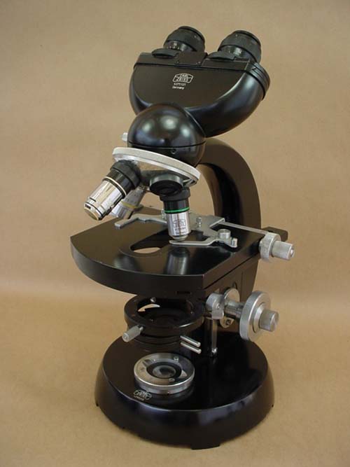
I was in love! The Zeiss GFL was everything I was looking for, beauty, style, grace, versatility, power steering and disc brakes, functionality and availability. And yes, it spoke to me with a familiarity of its wonderfully executed art deco spherical design and a comfort from what I instinctively knew was precise engineering. This definitely was the binocular scope I had to have.
Fig 1 The Zeiss GFL
Entering “Zeiss microscope” in eBay netted four pages of listings and there were several GFL scopes there, but there was a problem, they all suffered severe cases of dismemberment. Like a Corvette in a chop shop, these scopes were obviously more valuable sold off for their individual parts than as a whole. Even the most complete scope still lacked a substage condenser, oculars, lenses, illuminator, and was still commanding a price of over $1200.00! Did I really want to get into this?
Of course I did. I was determined to play Dr. Frankenstein and assemble a living, breathing GFL from parts, the final assemblage customized to my specifications, and do it for less than the cost of a complete scope. My goal was under $800.00.
The process began with the purchase of the GFL arm with quadruple objective turret and substage condenser holder (see fig 2) Previous arms like this with a base but no condenser holder were going for about $150. Somehow I got this one for $79 and from the same seller I got the binocular head for $75. Still needed were the base, condenser, stage, illuminator assembly, eyepieces and objectives.
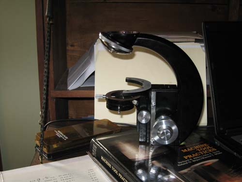
(Fig 2 the arm as received, nothing seized and all functions working very smoothly)
The 1.3 NA Zeiss condensers were going for about $70 to $100. I saw a $39 “buy it now” offering but the description said it had a small scratch. After a day I inquired about how bad the scratch on the lens was and was informed the scratch was not on the lens but on the chrome on the flip out mount. I now had a condenser and the lens was perfect.
The base was the next logical step so I could stand the durn thing up. It also seemed the most difficult. There was an extensive truancy on eBay of this fundamental foundation for the GFL, at least one that was not attached to another arm or an almost complete microscope. In fact, all of the other remaining items I required (rotating, centerable circular stage, light source and objectives) were selling at such premium prices I stopped to re-think this endeavor.
I consulted Captain Morgan and lapsed into deep contemplation and thoughtful analysis and after three or four seconds had my solution. Except for the objectives, I could manufacture everything I needed in my shop. This would be an excellent opportunity to expand the lighting capabilities and versatility of the scope in general. The final product however, must be commensurate with the Zeiss level of quality. That was a tall order.
The base is complete and the stage about 90% done. For those who may be interested, the rest of the article goes into some detailed description and photos on how it was accomplished.
The Base
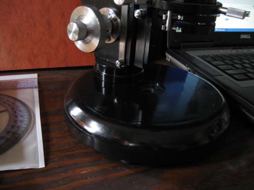
The original Zeiss base is a cast, hollow round section of a sphere with the light source built in. The arm attaches with four small screws and does not allow for any inclination of the entire scope. We are about to change all that.
The scrap bin at my work site provided all the required material, which is 6061-T6 aluminum. We use this stuff for a lot of fabrication, has a structural strength approaching mild steel and has excellent machining properties. My base was going to be solid aluminum and a larger diameter than the original thus giving more weight and stability. The arm would be attached via a fairly quick release interface that would also give more clearance below the substage condenser and rack mechanism for insertion of as yet to be determined filters, mirrors, prisms, diffusers etc.
To get the proper thickness I had to laminate together a piece of ¾” and ½” thick by 10” wide bar stock. The Navy Research Lab provided me with an epoxy that was stronger than the aluminum and had the same coefficient of expansion. This was trimmed with a saw to a roughly circular shape (see Fig 3), a center hole drilled for a bolt and then chucked in my lathe. Outer diameter was turned round and both sides of the disc were faced so as to be parallel and the final touch was to round the base upper edge to approximate the Zeiss design. This whole process took about 8 hours over two days. (I was working at the size limit for my small lathe and had to make numerous light cuts.)
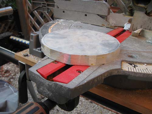
Fig 3
Next was the arm interface. I took a 3” diameter “plug” cut with a hole saw from a 1” thick piece of aluminum plate, center bored, threaded and counter sunk a hole for a flat head screw, and turned it down to just slightly larger than the arm base mounting surface. The tricky part here was to accurately transfer the arm attachment screw hole pattern to the interface, drill and counter bore the hole from the bottom of the interface to match the shell thickness of the original base so I could use the original screws. The last was to lock in the large flathead screw with a drilled and tapped hole for a setscrew flush with the top of the interface.
The interface was connected to the base by simply drilling a hole thru and counter boring the bottom to accept the nut and washer. Three rubber feet were then screwed in to the bottom of the base. The whole thing dissembled and painted with black enamel and left to bake on in the hot Florida Keys sun.
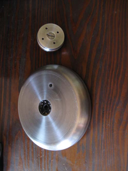
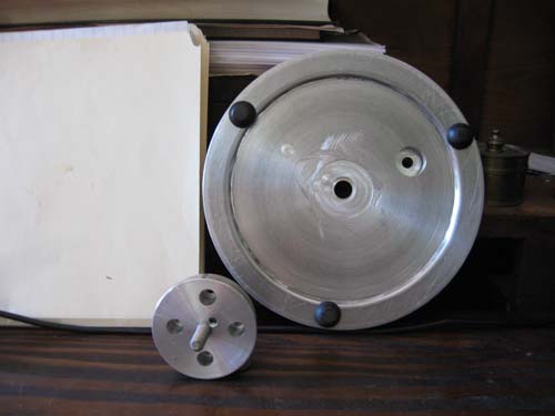
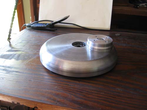
Figs 4 - 7
This whole business took two weekends to complete but thankfully, due to my personality, there are huge gaps in my social calendar and I can use the free time to my advantage.
The stage
This was going to be a bit more complicated. I had no Zeiss stage to copy from and the mounting hole pattern had to be exactly positioned in relation to the center of the stage, which in turn had to coincide with the centered position of the condenser. Taking gross measurements from the scope I made a full size cross section drawing of what I thought the stage should look like and would use it to take my measurements from for the machining process.
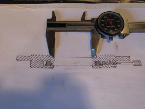
Fig 8
I visually centered the condenser and took measurements around its mount to fine tune it, then did a “rubbing” with pencil and paper to act as a marking template. Using my SF Stereo scope I was able to then accurately find and mark the center of each mounting hole and condenser.
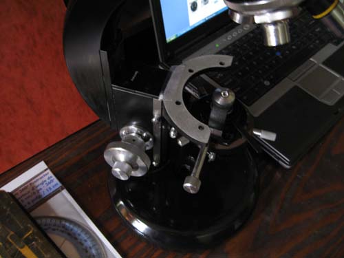
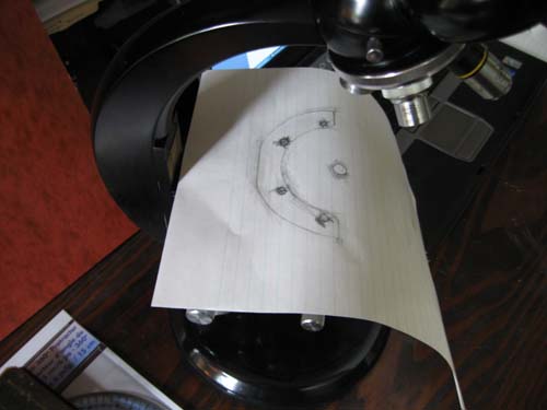
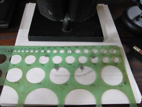
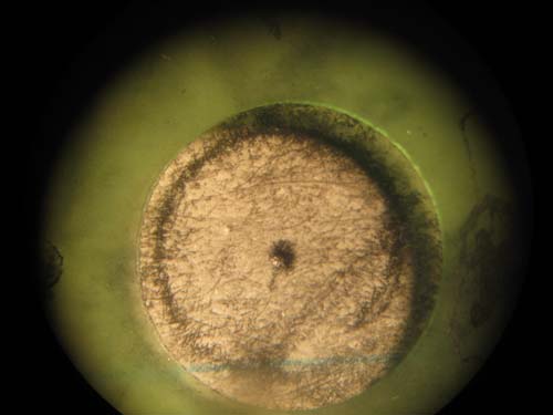
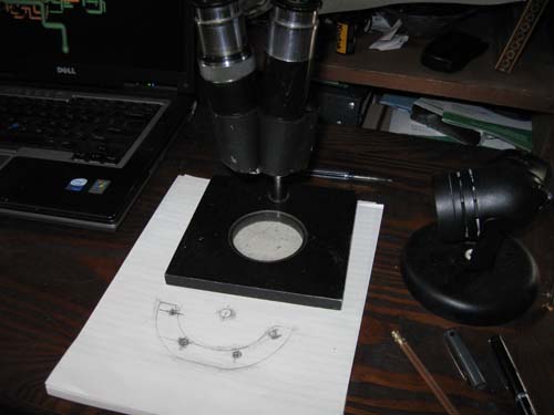
Fig 9 - 13
Laying the paper on the aluminum, I center punched the pattern for the holes. Accuracy was within .05 in. Good enough for my purposes and I began the turning of the stage base, the most crucial part. The stage base was machined from aluminum thick enough to accept the centering screws and the adjustable rotation brake/lock.
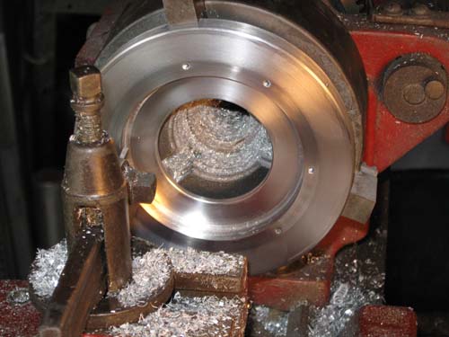
Fig 14 turning the stage base
After a test fit of the stage base, the inner bearing was cut from some schedule 80 aluminum pipe and then the rotating stage itself. The bearing to stage fit is crucial for proper operation and the final machining of the mating surfaces for the proper sliding fit had to be done with 1200 grit abrasive paper. The final result was a perfect fit with absolutely no play or wobble and an ever so slight resistance. A light coat of white lithium grease was the final touch.
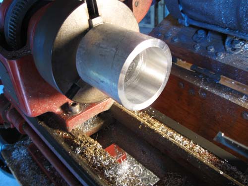
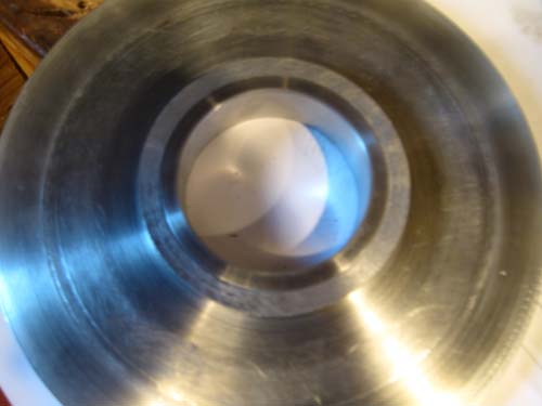
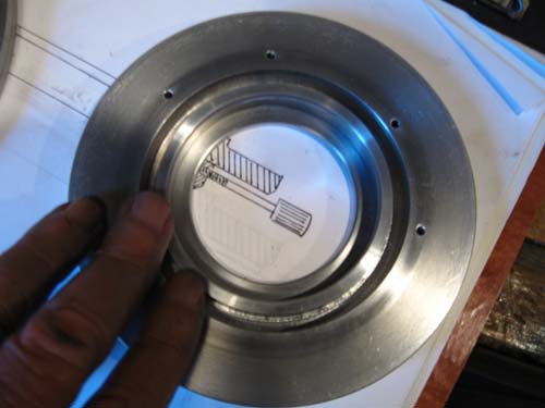
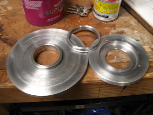
Fig 15 - 18
The adjusting screws were the next hurdle. Backlash would be the main obstacle to overcome in a set up like this. Long thread engagement and a good class fit of the thread is the solution for most high use applications but since that requires more precise tooling than I had available and the fact that these would see very little use after the stage was properly centered there was a more practical solution.
First I marked and drilled thru the stage base at the three spots for the centering screws and a fourth for the locking screw. These holes were as large as I could comfortably make it without affecting the structural integrity. Then some brass rod was turned down until it fit snugly into these holes. Sections of this rod was then drilled thru lengthwise and tapped.
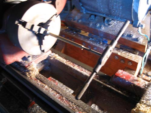
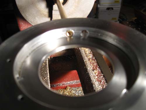
Fig 19 - Fig 20
From these I cut to length what would become the inserts and adjusting screw barrel shafts. Then a 4-40 screw was placed in one end of the barrel shaft, the excess cut off and the end turned round and polished. A knob of Zeiss-compatable design from some discarded electronic equipment was affixed to the other end. Now the threaded insert was screwed over the exposed thread and the class fit was adjusted by gently tapping around the malleable brass insert with a small hammer until all play was removed but the screw still turned smoothly without excess force. The insert was then unscrewed, placed in a hole and locked in place with a setscrew whose threads just gripped the insert from the side.
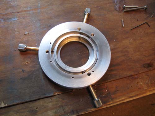
Fig 21
The front spring loaded centering pin is shown disassembled below. The spring and pin came from a discarded VCR (I take all these throw away items and disassemble them for parts).
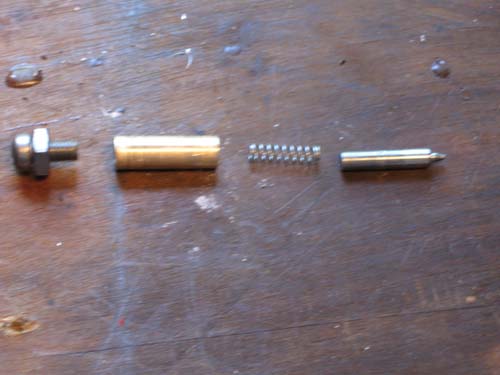
Fig 22
The bearing piece was then drilled thru to allow the brake/lock shaft to screw against a small, oiled leather “brake shoe” to adjust rotation resistance.
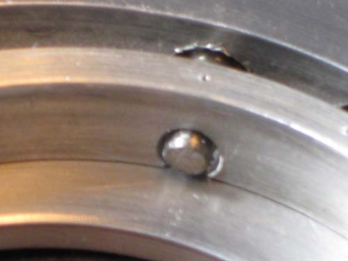
Fig 23
With the thus far completed scope and stage attached. I did a preliminary centering check with a 20x objective and all seemed well but need to do a little fine-tuning with the 40X objective. Some other minor tweaking for condenser clearance, a degree scale, and mechanical stage attachment remain. (Speaking of a degree scale, does anyone out there have an already made CAD drawing or similarly done rendering of a degree scale they would be willing to share?)
The whole stage fabrication to this point has been three weekends of work (I coulda made a stationary stage in one day but nooooooooooo, I had to have one with all the bells and whistles). So far the total cash outlay for the arm, condenser and binocular head is $193.
Illumination
As a simultaneous effort to the above (just to prove to my wife that I can multitask) I dedicated some of my vast mental capability to addressing the remaining lighting requirement. Most of the GFL stands I have seen have the light built in to the base but some have a small illuminator that sits on top of the base. The now solid aluminum base precluded my applying the former and I did not want to give up the substage space to the latter. In either case there was not enough flexibility to accomplish all the different applications I had in mind for photon manipulation.
An external source directed thru the condenser via prism or first surface mirror seemed to be the answer. My perusal of the external light source offers on line left me unmoved as they were either hundreds of dollars, not powerful enough, not complete, did not have complete range of adjustments (centering, focus, iris), hard to get bulbs, needed odd voltage power sources which were also expensive etc. etc. etc.
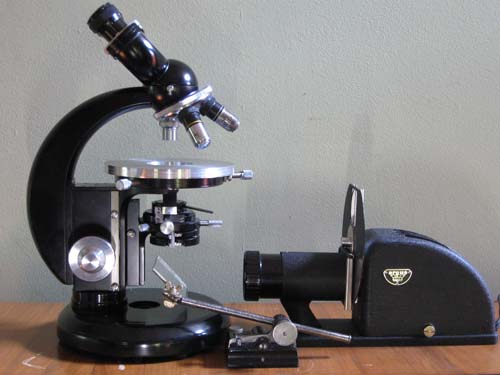
Salvation (at least I hope so) arrived in the form of Mr. Frithjof A.S. Sterrenburg of the Netherlands and his article on making a “Heavy Calibre” microscope lamp from a 35mm slide projector (Micscape Oct. 2002). His article made a lot of sense. These things are plentiful, inexpensive and I was able to find a black vintage projector in mint working condition with an Art Deco design that complimented the GFL perfectly for $9.99 plus $12.00 shipping. I was the only bidder. Below is a picture of the Argus 100 watt projector I bought.
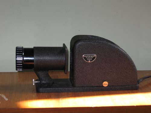
Fig 24 Argus projector
By affixing this light and the scope to a common base I could lock in the alignment and there were enormous possibilities for combinations and placement of neutral density and color filters, frosted glass and an Iris diaphragm.
(Fig 25 a congeries of congruous conjointment if I ever saw one)
This was starting to become a whole “system” so to speak, for microscopy. Vanity has enticed me to give it a name of its own such as the Ortholux, Axiophot, and Amplival have. What to name it? Since Captain Morgan left the building I consulted with Jack Daniels to ponder the question. It had no built in camera, so I couldn’t use “Phot” anywhere, and besides, the name was already taken. Since it had a powerful light source I considered “The Illuminator” but that sounded too much like an Arnold Schwarzenegger character. Hmmm…the two main components were the Zeiss GFL and the Argus light source, so let’s see… if we combine Zeiss and Argus by taking the first two letters of Zeiss and the last two of Argus we get… “ZEUS”!! Yes! That was it. Zeus, an ancient name, a powerful name, a Greek god, said to be ruler of Olympus so I figured he had it all over Leitz and Nikon too. “The Zeus whole microscope system.” A wonderful name and much more dignified than combining them the other way around which would have resulted in the word “Arss”.
Unlike Mary Shelly’s tortured Doctor I am not yet ready to scream to the heavens of my creation “IT’S ALIVE! IT’S ALIVE!” Much work remains. I hope to have Zeus finished in another month or so providing I am not overtaken by circumstances. A new set of four aftermarket DIN Plan Achromatic lenses is on the way. So the total at this point with the lenses and 10XWF eyepieces is $465.00. Still needed are the ND, Polarized and UV filters, mechanical stage plus the iris diaphragm with mount and the prism with holder.
So as another Episode concludes and a new year is upon us I would like to take this opportunity to thank the editor’s of Micscape for their patience and forbearance in allowing me to share my sometimes-outlandish pedagogic points of view. My wife, Chauncey Tubbs and myself send everyone best wishes for a fruitful and enlightening 2010.
For Christmas my wife presented me with a copy of “Robert’s Rules of Order” to enhance our evening conversations and possibly make me more receptive and democratic in allowing her to complete her “recitations of respectful criticism” before rudely interrupting. With this charitable attitude I encourage you to send me your thoughts or questions at gwilhelm@seawardservices.com
Happy trails. Comments can be addressed to me.
Joseph Wilhelm
Published in the January 2010 edition of Micscape.
Please report any Web problems or offer general comments to theMicscape Editor .
Micscape is the on-line monthly magazine of the Microscopy UK web site atMicroscopy-UK
© Onview.net Ltd, Microscopy-UK, and all contributors 1995 onwards. All rights reserved.
Main site is at www.microscopy-uk.org.uk with full mirror at www.microscopy-uk.net .