The Compound Microscope - A Brief IntroductionGregor T. Overney, Ph.D.Sunnyvale, California, USA |
|
|
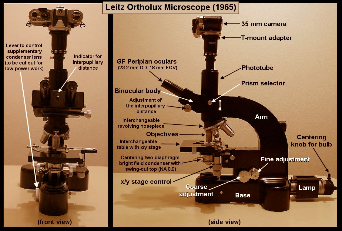
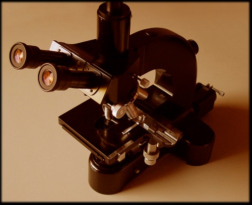
IntroductionWith this article, I introduce a few important components of the compound microscope. A summary of different ways of illumination in compound microscopy is presented. I also show the objectives (dry and immersion objectives), the ocular (eyepiece), and the condenser. I briefly introduce special optical components, such as the phase centering telescope and the projection eyepiece (photo eyepiece). Following the definition given by Bradbury and Bracegirdle in "Introduction to Light Microscopy", Bios Scientific Publisher, Springer Verlag, 1998, page 43, we learn that "a compound microscope is one [an optical system] in which a real magnified image produced by one lens (or lens system) called the objective is further magnified by another - the eyepiece - which typically forms a final, magnified, virtual image for observation by the user's eye." The authors mention that although stereomicroscopes and macroscopes could also be called "compound microscopes" based on this definition, they are not. It has been suggested that historical reasons keep stereomicroscopes and macroscopes out of the group of compound microscopes. A compound microscope is made out of various mechanical and optical components. It is a precision instrument. The performance of a good scope depends on good mechanical parts and excellent lenses. The anatomy of an older research microscope, the Leitz Ortholux, is depicted in the following picture. (You can click with your mouse-cursor on this picture to obtain a larger image.)
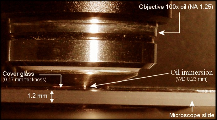
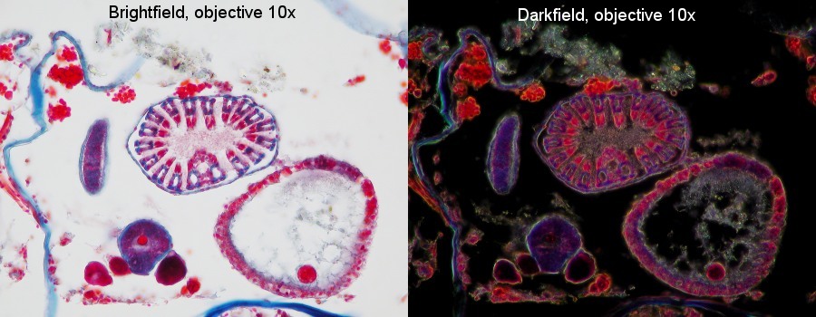
When light is generated by the lamp filament of a compound microscope using illumination with transmitted light, the light first passes through collector lenses and filters and then through the condenser, microscope slide, specimen, cover glass (if available), objective, and ocular. Finally it enters the observer's eye(s). Of course, additional filters, prisms and a so-called tube lens might also be necessary to complete the optical setup of a compound microscope. For instance, for so-called "infinity corrected" optical systems, a tube lens is added between the objective and the ocular. - It is important to keep in mind that the resolution of a compound microscope also depends on the relative position of all its optical elements and not just on the quality of each individual component. For instance, a microscope with excellent objectives and a great condenser performs rather poorly if the front focal plane of the condenser (location of the contrast iris diaphragm) is not "in focus" with the back focal plane of the objective. Or with other words, the back focal plane of the objective and the front focal plane of the condenser must be conjugated aperture planes. Different ways of illumination in compound microscopyIn the following, I restrict this introduction to a standard setup where the image-forming optics is above the stage (no inverted microscope). Before looking at some of the optical parts of a compound microscope, I want to summarize the different ways of illumination used for this type of microscope. - First, I subdivide them into different directions of illumination, or with other words, the way the light has to travel before it is diffracted and/or refracted by the specimen. Then, I further subdivide them into all the different methods to illuminate the specimen. And last but not least, I can further subdivide them into a few basic types. A setup using transmitted light is not the only operational mode for compound microscopes. The light can come from two distinct directions. If the light passes through the microscope slide and then is diffracted and/or refracted by the specimen, it is called transmitted light (diascopic illumination). But if the light comes from the direction of the objective, it is called incident light (episcopic illumination). In addition, special filters, prisms, and other optical components are used to create a multitude of different ways to work with a compound microscope. Essentially, there are at least nine methods to illuminate a specimen. These are:
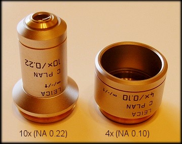
An example of method #1 (showing a stained Volvox aureus) is depicted above. (You can read more about Volvox in Ken Jones' Micscape article, which can be found at http://www.microscopy-uk.org.uk/mag/art97b/volvoxms.html.) - These different methods of illumination are further complicated by at least three different types or modes of illumination, which are known as diffuse, critical and Köhler illumination. It is obvious that some of the methods listed above can only work with certain types of illumination. - It is beyond the scope of this short introduction to outline the differences of these types of illumination. For now, just keep in mind that most low-cost compound microscopes are using diffuse illumination. (Unfortunately, not all microscopists understand the difference between diffuse illumination and critical illumination. While the resolution of an optical setup suffers when using diffuse illumination, critical and Köhler illumination provide the same resolution. However, only Köhler illumination provides also an even illumination, while critical illumination does usually not evenly illuminate the specimen.) - For most applications using compound microscopes at high magnification, I strongly recommend Köhler illumination. But for "low power" objectives (see below for more information about "low power" objectives), diffuse illumination is more appropriate. It is also worth mentioning that most compound microscopes, which "support" Köhler illumination, contain a diffuser, usually a frosted glass, just before or after the collector lenses of the lamp. While such a frosted glass enhances even illumination for "low power" work, it degrades slightly the resolution for "high power" work. In paragraph "The condenser" (see below), I will talk more about brightfield and darkfield using transmitted light. The jewels of every compound microscope - objectivesThe lion's share of the value of every good scope are the objectives. When the objective does not perform, the microscope cannot offer an adequate performance.
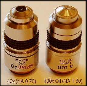
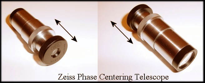
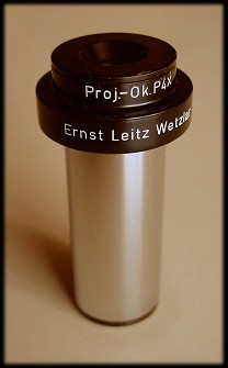
BTW, numerical aperture (NA) is a geometrical parameter related to the light-gathering power of an objective or other lens elements. NA is a primary determinant of the spatial resolution (high values for lenses with great spatial resolution). The maximum value for NA is 1.4 when critical or Köhler illumination is used. But for total internal reflection fluorescence microscopy (TIRFM), which is yet an other type of illumination, Olympus offers an objective with a numerical aperture of 1.65. The ocular or eyepieceThe closest group of lenses to our eyes are those lens elements that form the ocular or eyepiece. The major goal of the ocular is to produce a virtual image, which can be processed by our eyes. (Remark: A virtual image is an image that cannot be projected onto ground glass.) There are many different kinds of oculars available. The magnification range of oculars is between 5x and 25x. Usually 10x oculars are used. It is also important to note that you should not combine just any ocular with just any objective. Very often, the right combination of ocular and objective offers the best correction for various lens aberrations (such as spherical aberration). Special kinds of ocularsThere are a few special oculars worth mentioning. The first one is called the phase centering telescope. This ocular has a movable lens, which allows the microscopist to focus on the back focal plane of the objective. This is important when centering Köhler illumination or centering the phase rings used for phase contrast microscopy (see picture below).
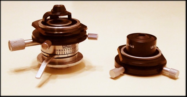
The condenserInteresting enough, this is the second most important component that directly impacts resolution. But it is also one of the most neglected optical parts on a scope. Just too often, the condenser is not appropriately utilized. - Basically there are two types of condensers. The ones that require oil immersion to achieve maximum resolution, and those we must use "dry" (without immersion oil). A very commonly used dry condenser has a numerical aperture (NA) of 0.9. The following picture (see below) shows two Leitz condensers. The one on the left side is called a Berek two diaphragm condenser. (Dr. Max Berek, 1886 - 1949, was one of the famous scientists working for Leitz.) This is an Achromat, swing-out condenser. The top of this condenser can be moved out of the optical path to create a more even illumination for low power objectives (2x and 4x). The condenser top depicted in this picture has an NA of 0.9. - The condenser on the right side is a special condenser (see image below). It is called a high-resolution darkfield condenser. A darkfield condenser ensures that no direct light can enter the objective. This type of darkfield condenser accomplishes this by creating a very wide cone of light (the inner cone has an NA of 1.20 and the outer cone has an NA of 1.40). Such a setup requires an objective with an NA not greater than 1.10. If the NA of the objective is larger than the value for the inner cone (here 1.20), direct light will enter the objective, which makes darkfield illumination impossible. Since this darkfield condenser creates such a wide and narrow light-cone, immersion oil must be put between the condenser and the slide.
I want to add a few more words about the high-resolution Leitz darkfield condenser. This type of condenser is also known as Cardioid condenser. This condenser is not trivial to operate and the following steps must be taken when working successfully with this unit:
Fortunately, if you plan to use a high power lens with a maximum NA of 1.25 or higher, you could just add a funnel stop in the back focal plane of the objective to lower its maximum NA to something around 1.10. You could also use a special high power lens with an iris. For low power objectives (and some high power objectives), you can also "convert" a brightfield condenser into a darkfield condenser by adding a patch stop as close as possible to the front focal plane of the condenser, which is the location of the contrast iris diaphragm. This patch stop will block out any light that could enter the objective without being diffracted and/or refracted by the specimen. It is important that you fully open the contrast iris diaphragm. The highest resolution of such a setup is around NA 0.7. Many manufacturers, such as Nikon and Zeiss, offer darkfield sliders that can easily be added to their low-cost Abbe condensers.
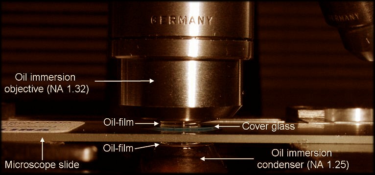
Let us look more closely at a condenser for oil immersion. We can often find this type of condenser on microscopes. The most common condenser is the Abbe condenser NA 1.25 (oil). To achieve this high resolution of NA 1.25, we must put a few drops of immersion oil between the top lens of the condenser and the bottom side of the microscope slide (see picture below). The depicted condenser is again a Berek condenser that was often sold with the Leitz Ortholux research microscope. This time, I put an oil immersion top (or cap) onto the Berek condenser.
|
Comments to the author, Gregor Overney, are welcomed.
Please report any Web problems or offer general comments to the Micscape Editor.
Micscape is the on-line monthly magazine of the Microscopy UK web site at Microscopy-UK