A Simple Rotating Stage Attachment for the Zeiss Axiostar.
and other biological microscopes.
By Ian Walker. UK.
Introduction.
If there is one thing I miss on a biological stand it's a rotating stage. As far as I am aware Zeiss do not make a polar version of the Axiostar nor a rotating stage as a retro-fittable part although you can purchase polarization accessories. I have built this for my Axiostar with its 15x11cm stage [working area] but the principle behind the design could be adapted to many other designs with a large stage. The only commercially built rotating stage attachment that I know of is supplied by Brunel Microscopes UK. This was tried but found to be far too thick for the Zeiss to focus since there is limited travel on the coarse focus controls of many modern stands and using it required the mechanical stage of the Zeiss to be removed. Those lucky enough to own lathes, pillar drills and milling machines plus all the materials necessary won't need to resort to my modest construction methods but at the end of the day I have a working system using common materials and once you return to using a rotating stage you wonder how you managed without one especially if one of your interests is crystal photomicrography. Photographic possibilities can be lost when a crystal or polar active slide is observed at a fixed angle, the best colours or attributes of the subject may be at any angle other than when the slide is held firmly in the mechanical stage so with this in mind I set out to make a rotating stage for the Axiostar.
Main aims of the stage.
1. Checking the photographic possibilities of crystals and polar active slides which are hard to manually rotate on a fixed stage and be good enough to photograph the subject with low power objectives with no loss of field flatness. If higher power objectives are needed the angle of the slide will be known and the rotating stage assembly removed, the slide being placed at the same angle on the main stage and the condenser and field diaphragm reset. I have used the rotating stage with higher power objectives but only when a lower power objective has first been used when rotating the slide but this is still not ideal due to the condenser not being used at its optimum setting.
2. Simple but accurate measurements when observing thin rock sections.
3. Mechanical stage of the Zeiss to become part of the design and not removed.
4. All parts to be easily sourced from household or D.I.Y. materials and the microscope 'junk' box.
5. To use a CD as the rotating stage, they are available free on the front of magazines or in newspapers and machined to good tolerances plus they are the right size for this project.
6. Good enough tolerances to be used with my 2.5x and 5x objectives which translates to a maximum of 50x visual magnification with the Zeiss 10x eyepieces and trinocular head.
Materials and construction methods.
**Since the construction uses sharp knifes and drilling of plastic the dust of which may be inhaled or get into your eyes make sure you take all necessary precautions before starting the work, if in doubt don't do it!
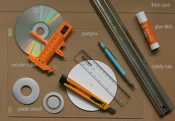
Some typical tools and materials needed to make the stage illustrated below.
Circular paper cutters are commonly known as compass cutters and a Google search will normally bring up plenty of craft shops selling them, they can also be found new on eBay for about Ł4.
The main criteria here is to experiment as much as possible with the base of the rotating stage with thin card to get the basic shape for your scope and the correct location for the bearing to accept the CD, the type of cardboard found on cereal packets is commonly available and easily cut to make a final template to work from and there is enough of it to have a few goes! Once you have the dimensions you can use a felt tip pen to mark out on a piece of Perspex or material of choice. I purposely used 1.8mm Perspex because it is rigid enough at this size and relatively easy to work with. With this thickness you can make the rectangular outline without sawing by scoring the Perspex several times with a sharp knife above and below and snap it by putting pressure on the unused part and holding a solid ruler over the part you wish to keep, this being held at the score line over a sharp angled surface like a kitchen work table. I have found this works well, gives very accurate cuts and requires minimal amount of finishing with a file to smooth off edges. Do not try and do perpendicular cuts the Perspex will shatter, just one line of the base at a time, the angled section and smaller dimensions I did with a small hacksaw.
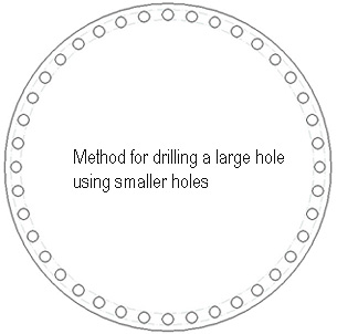
I have no large drills so the 26mm diameter hole was drilled out by making a number of much smaller holes in a circle within the 26mm diameter and then use a needle file to connect them all up and just push out the middle section, make sure the holes are within the required diameter and use a gently curved large file to make the hole round, if you do this accurately little filing is required. Since I was also dealing with a hole much larger than the hole in a standard CD this method was used on the CD as well and the plastic drills well but keep dust and chaffing's out of your eyes and fingers. If the hole for the bearing in the CD has been well made you should be able to spin the CD freely on the bearing with minimal eccentricity, tight spots or slack, it is this slack which is to be avoided since whilst turning by hand the subject will appear to 'jump' when your finger is offered upto the edge of the rotating stage. All is not lost if the hole drilled is too large for the bearing on the CD since the bearing can be enlarged by one turn of Sellotape or preferably very thin plastic wrapped around until the CD turns smoothly without slack or friction or you can start again with a new CD! Contrary to what may seem obvious not all CD's are flat some are slightly warped, others have more substantial build and stiffer so if you have a number of 'freebies' to select from, check this first and select the best one.
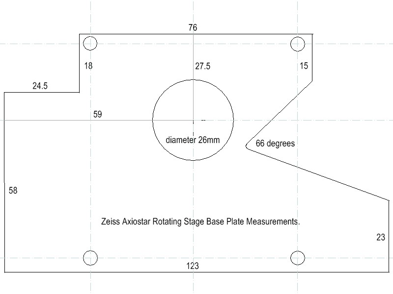
On the left, rotating stage base measurements for my Axiostar, all dimensions in mm, this is a good starting point but you may have your preferences and improve on my design. Click on 'base' image for a larger version, the right schematic is for illustration purposes, the amount of holes and their size is of personal preference but drilling them too close together or large can cause the Perspex to shatter or crack unpredictably, the final connecting of holes is best done with a needle file.
Early tests with the design.
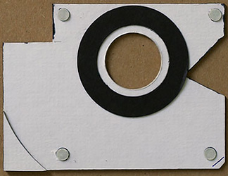
On the right, the prototype circular scale for the rotating stage drawn with Rotring drafting pens and Letraset for the figures this is based on paper stuck to thin card and this was just laid onto the felted CD surface not attached to the edge. On the left, part of the prototype base plate made from 1.6mm thick card minus the metal ring for the bearing assembly which is in use on the later version, this is where all the main problems and fine tuning of the design were carried out before moving onto cutting the Perspex [or material of choice]. However you don't have to use this thick card for your template I actually used a working prototype for a while to check the viability of the design before moving onto a Perspex version. Cardboard does not have the stability needed for continuous use and warps under different temperatures and humidity. The black card ring supported the center part of the CD and the grey roundels prevent rocking whilst turning by hand these are also used on the final version they are made from 0.5mm thick card using a paper punch and are topped with very thin plastic made the same way to prevent friction whilst turning.
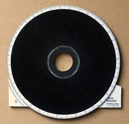
The top of the completed rotating stage. The black felt came from the lining of an old presentation box of knives and forks, this had a thin plastic base to glue to the CD and just the right thickness and 'feel' for supporting slides, you could use the circular cutter to make a mat out of card but there needs to be a raised portion for the slide to rest on so the plastic ring in the centre does not snag on the slide when the stage is rotated. An arbitrary marker is placed at the left hand corner for reading the scale which on this version was made using the Turbocad CAD package and printed out making for a professional looking finish and accurate measurements if needed. The centre shows a thin black plastic ring sitting just beneath the level of the felt this holds the CD in place, prevents wobble on rotation and is super-glued to the bearing made from a 1.5mm thick 26mm outside diameter aluminium ring.

Underneath of the rotating stage, the various cut-outs roughly follow the contour of the mechanical stage assembly on the Zeiss providing support with minimal movement, [see below]. One of the most important design elements is the plastic centring piece shown; this allows the rotating stage to be located accurately in the cut-out for the condenser found in all transmitted light microscopes, the shape and size of this will depend on the design of your microscope. There is about 1mm clearance in the condenser cut-out when it is correctly located and provides a consistent and easy way to find the only place in the 'X' direction where rotating the stage will not cause the required part of the specimen to rotate out of view. With the 'X' position fixed and accurately located the 'Y' position can then be found easily and recorded which in my case reads 27.2 on the vernier together these two settings provide an accurately centred stage which on rotation any part of the subject selected in the centre of the field of view on the slide remains in view.
You can just see at the left hand cut-out the grey slip ring made from a very thin plastic sheet found in some A4 file dividers but any similar plastic sheet will do provided it allows free rotation and provides about 0.5mm height clearance from the CD to the base preventing scuffing. The aluminium ring can be seen forming the bearing this came from a standard 23mm eyepiece where sometimes you will find them to raise the eyepiece in the eyepiece tube about 5mm but this can be anything similar to hand and the diameter is not critical since you can drill the CD to take a quite large hole if needed. A ring that is a good fit in the original CD hole is a good choice since this is already accurately centered but I could not find anything suitable however the diameter is governed by the condenser design; you must have a hole large enough to let all the light from the condenser through for your lowest power objective otherwise it will act like a light stop.
Design on the microscope.
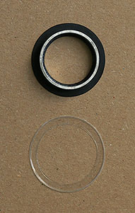
On the left, the rotating stage base with the CD lifted off showing how the cut-outs fit the mechanical stage assembly on the Axiostar and on the right, the bearing and upper slip ring. The uppermost surface shown here on the aluminium ring is a tight friction fit into the base and is adjusted by hand to be a compromise between ease of spin and wobble whilst being rotated. If I was to make another version [see addendum] the rectangular cut-out for the Zeiss mechanical stage would be an even closer fit and the angled section near the swing arm a little closer to the arm. The corner card sections with markers and name plate are not essential and can be left off for simplicity.
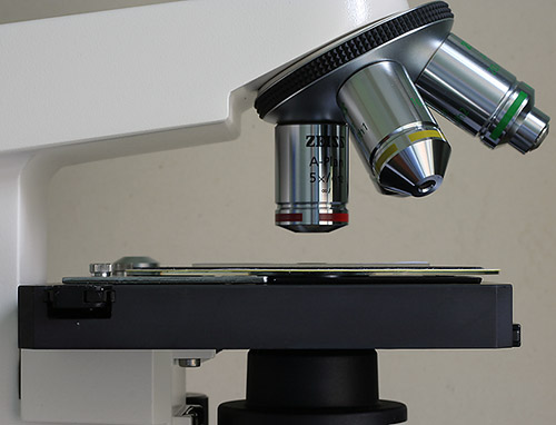
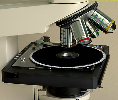
The CD based rotating section just clears the mechanical stage control, this is achieved by slip ring[s] placed beneath the CD and the choice of thickness of Perspex which roughly matches the aluminium Zeiss stage control, minimal height of the assembly was a high priority to achieve the best stability from the lightweight construction and minimum light fall-off from the condenser and since the field iris cannot be focused by the condenser this is left wide open with minimal effect on image quality at low powers whilst the condenser iris is adjusted for best contrast which for the A-Plan objectives is about 90-95% full aperture using brightfield or crossed-polars. The condenser is racked to its highest point whilst the base is held in place by cut-outs and the powerful sprung arm on the Zeiss. For a guide of thickness there is a slide under observation on the stage and note this picture is taken with the 360 degree scale removed.
The stage in use.
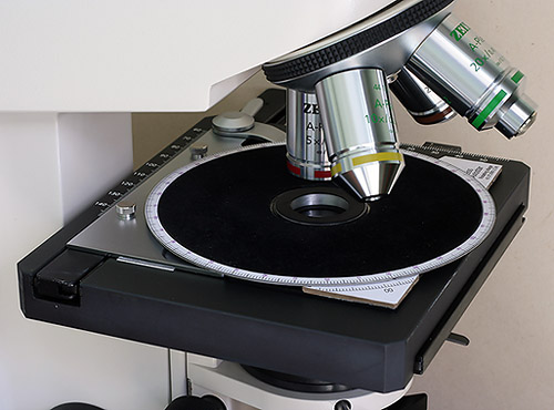
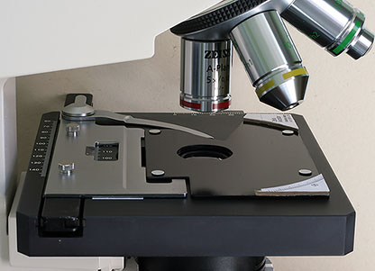
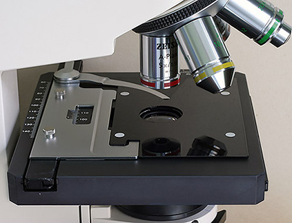
The finished rotating stage fitted to the Axiostar, note the overlap at the front of the Zeiss enabling precise movement, most convenient point for rotation with minimum effort and importantly can be adjusted easily whilst the subject is under observation. Once in place the Zeiss 'X' and 'Y' stage controls are not touched, all slide manipulation is done by hand which for low powers is not a problem and is in fact a benefit for large crystal preparations allowing quick scanning of interesting areas. Note the continuation of line from the aluminium Zeiss stage plate at the rear to the corner of the new assembly forming a large square for the best aesthetics and logical use of stage area. The thin white line on the Zeiss stage serves as the calibration point in the 'X' direction for offering the rotating stage upto the Zeiss otherwise I would have to read off the vernier which is awkward. In this position the stage can be fitted to the Zeiss and the two 'lock' together using the condenser cut-out in the Zeiss and my centring piece fitted to the underneath of the base on the rotating stage assembly. Tests can be done with a test slide like a grid slide or well prepared botanical section to test for possible field flatness problems, ie: the CD is tilted, by rotating and regular checking as you go round, mine is good enough to be used in place for photomicrography with my 2.5x and 5x objectives beyond this I would remove it and place the slide at the same angle [if possible] on the Zeiss stage and reset the condenser to its correct position.
Was it worthwhile? I think so, it's been in constant use since I've built it and opens up more photographic opportunities and measurements with thin sections compared to a fixed stage and can be removed in seconds without modification to the original stage. I am still considering 'fine tuning' the design but the basic idea stands and making a base and fitting the CD should take no more than two or three hours using the methods and materials suggested.
Thin rock section Gabbro from OU260 slides.
The following images were taken with the A-Plan 2.5x objective and Canon 350D DSLR body via the Zeiss SLR relay lens, they are scaled from the full 8Mp image size with virtually no cropping showing good sharpness edge to edge. The 350D was set at 100 A.S.A. and has a mirror lock combined with self timer these were used together with the in-camera histogram function on playback to check for good exposure.
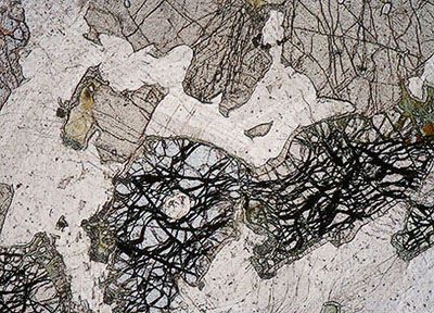
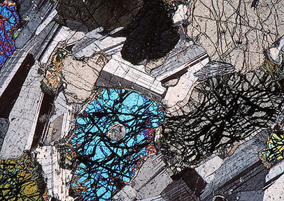
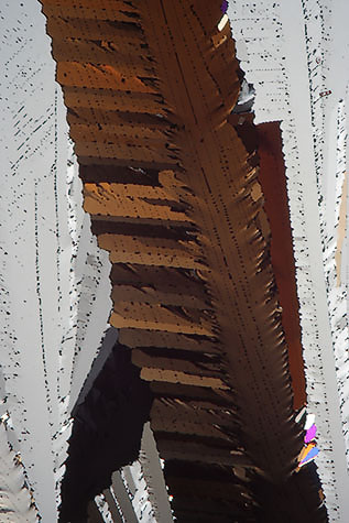
On the left an image of gabbro from Scotland showing a large crystal of olivine with imperfect cleavage this is taken under plane polarized light with an analyzer in the vertical position and polarizer removed. On the right the same image using crossed-polars, the olivine is now showing second order blue interference colours whilst an adjacent piece of olivine which appears to be attached is at a different orientation and only showing low order colour. The olivine is mostly surrounded by plagioclase feldspar showing some characteristic multiple twinning. The large crystal in the top right hand corner with good cleavage is probably clinopyroxene often associated with gabbro.
Resorcinol.
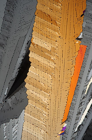
Here are two images of resorcinol prepared by the late Eric Marson, N.B.S. ref 115 to show the difference about 30 degrees can make when rotating a crystal slide - surely a good reason to have a rotating stage!
Addendum.
As mentioned above I was considering making a more refined version of the base which was finished after the bulk of the article was completed. You can see now the swing arm fits the contour exactly at the rear of the picture and the cut-out at the front is now a 'locking' fit. This does not affect the validity of my base in the main text which works fine as is. This version is harder to make because instead of sawing the cut-outs they were made by drilling a series of small holes and connecting up as in the circular hole for the bearing, this is the only way of making a gentle curve and a more complex cut-out with the tools I have but it is more demanding and time consuming to make.
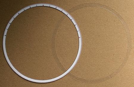
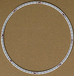
To complete the rotating stage I made two further rings, the clear plastic one fits over the 360 degree scale to protect from finger marks due to printing by bubble jet which are more prone to smudging this is not glued and can be removed to allow the second calibrated ring to placed over the existing scale. This scale is marked 80-00-80 degrees and can be reset to '00' at any point of rotation of the stage and is useful for direct reading of extinction angles when observing thin rock sections.
the end.
Comments to the author, Ian Walker, are welcomed.
Please report any Web problems or offer general comments to the Micscape Editor.
Micscape is the on-line
monthly magazine of the Microscopy UK web
site at
Microscopy-UK