|
Making an Antoni van Leeuwenhoek microscope replica continuation of ' Making a Van Leeuwenhoek Microscope Lens ' by Hans Loncke, the Netherlands |
|
In an earlier article I showed how I made small lenses and how I calibrated them. After so much improvising and work on lens making, I considered whether to make an Antoni van Leeuwenhoek microscope replica.
Shall I make
the other parts and treat myself to an
A.v.L mic' replica? Before doing that, I
want to know if the lens will produce a
satisfactory image. If not, proceeding is
useless. What would the image quality be?
How do I check that? Heh you, hold the
lens steady for me, and keep a preparation
exactly in focus, so I can make a picture?
That won't work. Searching for a suitable target, I aimed the microscope's flat mirror onto the houses on the other side of the street, then found the image of the lens-under-test. The slanted microscope mirror causes the oval cutout image. I focussed the microscope onto a car and garages at about 65 meters distance and with a Coolpix 995 camera made a picture (fig.1) . The smudges at the circumference are caused by bad spots in the photo-eyepiece. |
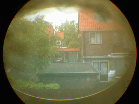
fig. 1 |
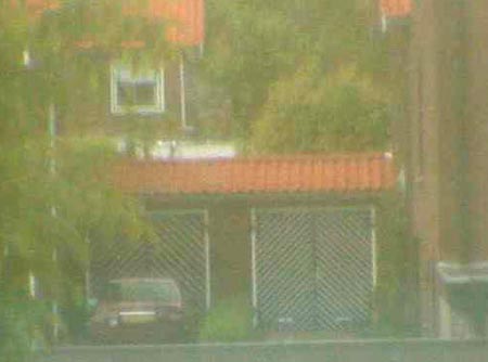
fig. 2 |
I went to the computer, enlarged the picture and to my surprise saw the white chevron lines on the garage doors (fig.2) . Imagine: a Ø 1 mm image, made by a symmetrical lens of only 3,7 mm focal length and 1 mm aperture! No complaints about image quality, I decided to make an A.v.L. replica. I had no drawn plans or sketches of the mechanical parts. But I live 25 km distance from the Boerhaave Museum in Leiden (the Netherlands), where there are four authentic van Leeuwenhoek microscopes on display. Measure them myself? Haha! The museum-staff would certainly not allow me to touch one of their treasures, let alone measure them. A difficult problem. A friend mailed me a 1996 drawing and instructions to make an American replica. Dimensions were in traditional and decimal English inches mixed. Oh, I’ll manage, but they apply a molten glass bead as a lens. NO! I will use my own ground lens. Then, at last, in a booklet, commemorating the 350th anniversary of the birth of Antoni van Leeuwenhoek, I find enough technical data and dimensions, to start work. |
|
Fig.3
gives an
exploded view of a van Leeuwenhoek microscope.
It consists of the upper body-plate (1), the
lower body-plate (2), the bracket screw (3),
the square bent main bracket (4), the main
screw (5), the stage (6), the specimen pin
(7), the focussing screw (8), the lens (9) and
five rivets 1,5 x 2 mm (10).
|
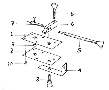
fig. 3 |
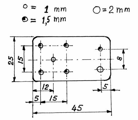
fig. 4 |
I start making the two body-plates (fig.4) , the plates that hold the lens in place. The body-plates of the nine surviving authentic A.v.L. microscopes measure 1 x 1 3/4 inches on average, that is 25 x 45 mm. The smallest are 19 x 22 mm, the largest are 28 x 47 mm. I did not find the thickness of the plates; I estimate them to be 0,5 mm thick. |
|
Of which
material shall I make my replica? I have
no brass sheet, so for the first trials I
took a piece of a 0,4 mm tinplate of a
baking oil can, a Christmas leftover. Not
a beer can or other drink can, as these
are only 0,1 mm, and that is far too
thin. |
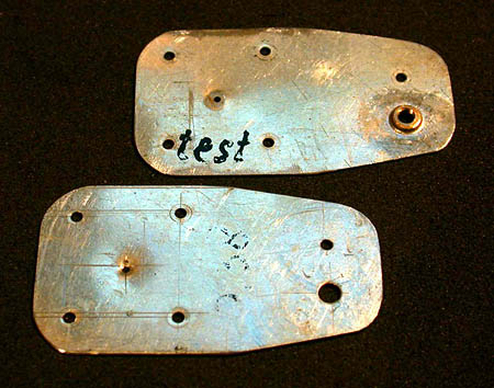
fig. 5 |
|
Upper and lower plates now have equal hole patterns. At the position where the lens will be held, the plates must be recessed a bit. The fastest way to do that, was by putting a steel bearing ball between the lens-apertures, holding 0,5 mm lead sheet on the outside of both plates, and then 'pressing' the assembly between a bench vice with smooth jaws. The ball should have the same radius as the lens. A recess of about 0,3 mm in each plate will do to form a useful chamber. If too deep, the lens will rattle and not have a fixed position; if not deep enough, the lens might crack! That is why I made more than just one lens . . . The upper and lower body plates can now be separated and must be marked to prevent mounting one of them inside out. On the upper body plate (the specimen side), a 1,5 mm high M3 nut must be soldered to the rim of the 3,2 hole. A filed down brass nut is temporarily fixed with an aluminium screw and with standard flux tin soldered to the plate. The nut must be thin; otherwise, later on, the main screw might get stuck (fig.6) . Eventually it may still be necessary to file it down a bit. After soldering, unscrew the aluminium screw and remove flux residue. It may be necessary to correct the corresponding hole in the lower body plate with a needle file. |
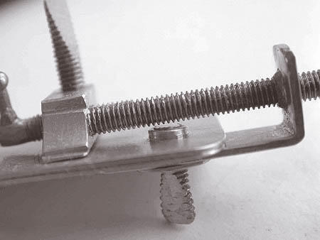
fig. 6 |
|
I wondered about the thread that van Leeuwenhoek used for his screws. Of the nine original A.v.L. microscopes, the screws are approx. 2,5 mm thick. Approximately, as I cannot measure them, they are all behind glass. Apparently nobody was interested in old screws, nobody ever paid much attention to them. In these nine original microscopes Antoni has used five different pitches on the screws: 0,46, 0,60, 0,67, 0,87 and 0,97 mm, that is 55, 42, 38, 30 and 26 threads per inch. Why would the maker of such ingenious little instruments use five different threads? There must be some reason. On his too and fro rotating spindle, he could not make screw threads. If he cut them himself, he must have possessed thread cutting dies and taps. Those tools existed already in his time, but were certainly not for sale in the tool-shop-round-the-corner or the supermarket. If his tools were lost or blunt, he would probably have bought new ones, but where? Or would he have his screws made by a clockmaker, perhaps the town’s clockmaker in the Delft marketplace? That might be, in view of the alarming low average life expectancy in those days, a new clockmaker every 10 to 15 years. And of course, every clockmaker made his own set of screw sizes. Standardisation of screws was introduced only since 1820/30 by Henry Maudsley and Joseph Whitworth. |
|
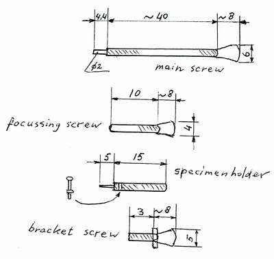
fig. 7 |
Had Antoni
discovered that focusing goes easier with
a fine thread rather than with a coarse
thread? The three still existing silver
microscopes (not the most powerful) all
have finer threads than the six brass
ones. But, yes, all three are
different!
Fig.7
gives all
the sizes of the four screws. They
are oversized, so I can always make
them shorter (not longer). For best
performance, the main screw should be kept
very straight. |
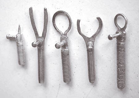
fig. 8 |
Van Leeuwenhoek made his specimen holder shaped like a pin. The specimen holder can be made as it is depicted ( fig. 8 left side). But I have difficulty fixing a specimen, so I made a few variations, of which I prefer the middle one. On it, I cement a Ø 7 mm cover glass with shellac and now can mount any specimen in water or balsam between cover glasses. Antoni did likewise, using mica sheets. |
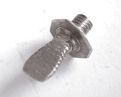
fig. 9 |
On the bracket screw ( fig. 9 ) a washer is fixed. It was made of 0,5 mm brass, cut 8 mm eight-sided and provided with M3 thread. |
|
For the bracket (fig.10 ) I took a piece of 1 mm brass sheet, 1,5 mm will do as well. I made the M3 thread a close fit with the main screw; the adjustment of the specimen works better with minimum play. |
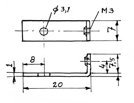
fig. 10 |
|
The difficult part of this microscope is the stage ( fig.11 ). It was made from bar brass. The 2 mm hole should be a fine fit with the Ø 2 mm bearing end of the main screw. In the final assembly the Ø 2 mm end will be riveted onto the stage, in such a way that the main screw can easily rotate with minimum play. Before riveting, some adjustments must be carried out. |
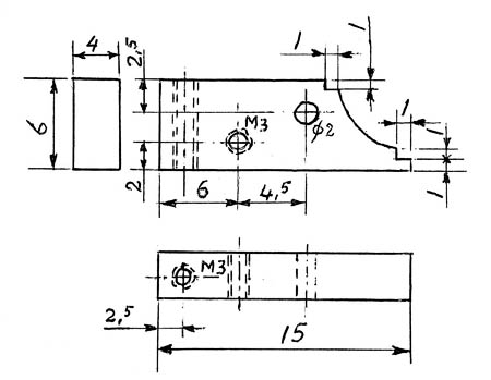
fig. 11 |
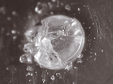
fig. 12 |
When all parts are ready, they are pre-assembled. I temporarily assemble the upper and lower plates, the lens in between, with five M1,6 mm x 2,5 screws and nuts and check that the lens stays fixed and does not rattle. I also check if the image quality is the same in both sight directions. The lens must be very clean, of course. If the image quality is not the same, try to find the cause. When that is correct, I replace the screws for rivets, one by one. If your hands are not too steady: be careful and try, not to hit the lens; I you do, this will be the result ( fig.12 ). I did not find copper rivets in a shop, so had to make them as well. Electric copper wire of Ø 1,5 mm can also be used. |
|
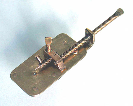
The working of
these parts has, in my view, never been
explained better than in 1886 by Mayall, whose
text I hereby cite: The long screw serves to adjust the object under the lens in a vertical direction, whilst the pivoting of the angle-piece on its thumb-screw gives lateral motion. The object carrier can be turned on its axis, as required, by screwing the rod into the stage (by means of a metal knob). When the rod is rotated by moving the the knob, the object is not only turned on its axis, but raised or lowered by the screw, passing through the block – thus forming a sort of “fine adjustment” for the “coarse adjustment” provided by the long screw. For focussing, a thumb-screw passes through the stage near one end, and presses vertically against the plates, causing the stage to tilt up at that end; the fitting of the long screw –carrier (angle-piece) is such that the stage at the end is sprung down somewhat forcibly on the brass plates, and it is against this pressure that the focussing screw acts.” End of quotation.
|
|
Before final assembly, a few tests and adjustments must be performed. I mount the bracket with the bracket screw, then insert the main screw through the bracket and into the stage and check that it is lightly pressed onto the upper plate. If not, I take the bracket and main screw from the lens plates and carefully bend the bracket and keep the main screw straight! Then I check that the main screw runs free of the bracket screw and the soldered nut. Then I mount the specimen pin (or fork) and check that it is in reach of the focal length; if not, alter it. Check that the focal adjustment screw fits in well. I unscrew the specimen pin and the focussing screw and remove the stage from the main screw. I add some damping grease (kilopoise 0868S, any other make will probably do as well) onto the Ø 2 mm end of the main screw and insert it into the stage again. It should poke out about half a millimeter. Then I clamp the assembly in a machine vice, in such a way that only the main screw is clamped and the bracket and the stage can rotate freely. For this operation I made a Ø 20 mm two part M3 holder (fig.13) to hold the main screw and at the same time support the stage. Then, very carefully, I rivet it so that in the end the main screw turns lightly in the stage with munimum radial and axial play. With some care this can also be done in a lathe. |
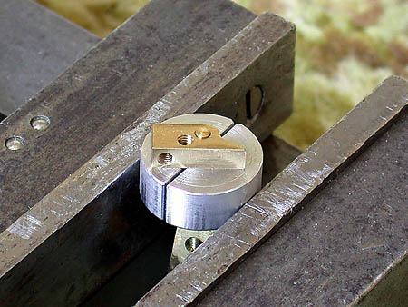
fig. 13 |
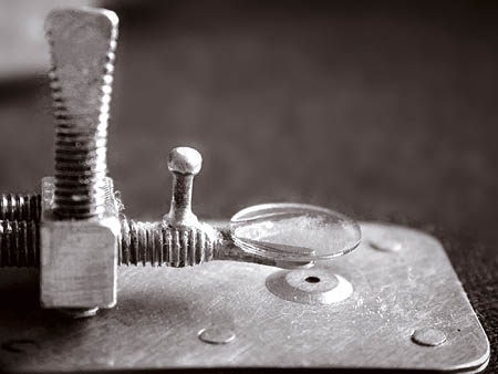
fig. 14 |
I also add some damping grease to the thread of the specimen holder and the focussing screw. Once more I check, that the main screw is free from the bracket screw, if not, the nut is lowered with a file. I now want to mount a specimen on the (fork)holder, so I first check that it will be inside the focussing range. It is, so I glue one of the special prepared specimens on the fork, using shellac ( fig.14 ). The preparation consists of strewn fossil diatoms from the Isle of Fur, Denmark, between two Ø 7 mm coverglasses. A few days later, when the shellac was dry, I took a few pictures through this x 69 A.v.L. microscope replica. |
|
Fig.15
shows two
Trinacria
species of about
0,1 mm size. Holding the microscope against
the lens rim of the Coolpix 995, making
pictures was as easy as that.
|
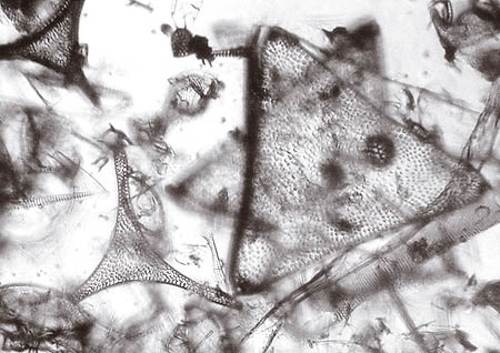
fig. 15 |
|
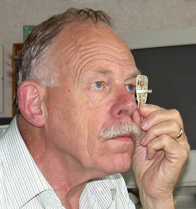
And this is the way the microscope is used. Not many people realise that Antoni van Leeuwenhoek made so many discoveries with tiny instruments just like these. |
Read Hans Loncke's earlier article about ' Making a Van Leeuwenhoek Microscope Lens'.