
By Ian Walker, UK.
A good source for further reading on polarized light microscopy with interactive tutorials and excellent graphics is on the Molecular Expressions website. This explains all the terms used if you are new to the subject, the site also shows a birefringence chart which is mentioned in the text.
By Ian Walker, UK.
..........
I have been interested in polarization microscopy for some time, however, finding a reasonably priced scope to include all the features that are useful for this technique can be frustrating. Buying much older, second-hand scopes on eBay or similar can be problematic since these scopes can use different polarization methods such as calcite prisms rather than polaroid sheet, which may be damaged, also if any of the parts such as dedicated retardation plates etc. are missing these may be very difficult to source. To buy a new polarizing scope from any of the 'big' names like Zeiss, Leica and Nikon you are going to have to spend an awful lot of money!
As an introduction to polarization I bought a boxed set of Open University (OU) S260 thin rock sections, these are of reasonable quality, and a low cost polarizer - analyser set, there are many other uses for polarization in microscopy but this seemed a good place to start.
Note. Professional thin rock sections prepared to the standard 30 micrometre thickness are often shorter than normal prepared slides or may be nearly square; this is to allow easier handling on a rotating stage which can have special fitted slide carriers that have their slide adjusters within the confines of the stage. Conventional slides may be used by the amateur or old Victorian mounters who prepared thin rock sections.
Read any book on polarizing
microscopes and it quickly becomes apparent how useful a rotating stage
can be especially if you start to get involved in identifying minerals
in thin section or looking at prepared slides of crystals. Without a rotating
stage you cannot check pleochroism, [the change in colour of crystals in
plane polarized light [just the polarizer in the light path] or easily
check the change of birefringent colours under crossed-polars, again useful
in identifying minerals in complex rock samples.
Some experiments in modifying a biological microscope for polarization.
Before I purchased a dedicated polarizing microscope [if at all], I wanted to find out how much can be achieved using a standard biological microscope by adding a few simple adaptations to make it more useful whilst spending as little as possible - this was the main criteria! The objective I've used throughout is a cheap 4x achromat with a good working distance. This together with a low power 5x or 6x eyepiece is ideal for starting out, more on this later. [I don't recommend 10x and above eyepieces for doing these tests].
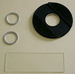
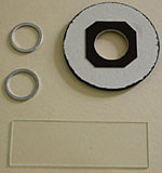
Fig 1. Top Fig 2. Bottom
Fig 1. above was my first attempt at building a rotating stage adapter for a fixed biological stage. It consists of a 3" x 1" slide, two aluminium cover slip mounting rings and a home made slide carrier designed for the shorter OU S260 slide set and is made from thick card.
Fig 2. shows the bottom which shows a polished piece of thin plastic glued on to the base which allows free rotation by minimizing friction on the slide. To build it I simply cemented accurately the two cover slip rings one on top of the other to the centre of the slide and placed the circular carrier over the rings. Depending on how much clearance you need for the circular stage above the slide carrier you may need to add some thick card to the bottom of the slide, see my improved version in Fig 4. [Note: some poorer quality card can be abrasive and could effect the finish on your stage.]
Attaching to your normal stage couldn't be easier since your slide carrier holds it in place but also allowing limited use of your X-Y stage controls. There is one basic problem with this method and that is there is only one 'sweet spot' on your stage where the crystals or minerals will remain in the centre of your field of view as you rotate the stage. This spot can be found by making a circular piece of card with a pin hole in the centre then put this centrally in the rotating stage and use the X-Y controls to bring this exactly central to the field of view. If you remember this point of reference you can the move the slide about within the carrier, but on rotating the selected crystal or mineral section it should remain within the field of view with objectives such as 3-10x with low power eyepieces; it won't be much use with higher magnifications.
Note. If you do not wish to experiment with building your own circular stage but like the principle you can buy ready made circular stages with calibrations to place on top of your existing stage, some of which include polarizer and analyser. However, these are normally quite large and are designed to have your slide carrier removed and on my scope the carrier is not easily removed and replaced, it requires a special tool but my circular stage cost virtually nothing and can be instantly removed to revert your scope back to 'normal'.
Shown below in Fig 3. is a very useful piece of kit that I picked up for a couple of pounds, without it experimentation is a lot more difficult. Basically it is a circular cutter that can cut card up to about 3 mm thick and plastic up to about 1 mm thick, exact hole diameters can be cut since it has mm calibration markings. It comes complete with a self-healing cutting board and spare blades. The picture shows how versatile it can be since you can also make dark field stops, field condenser stops for a lot of the modern cheaper scopes which don't have them fitted and coloured filters to fit any filter holder etc. These should be available from any good drawing or artist supplies shop.
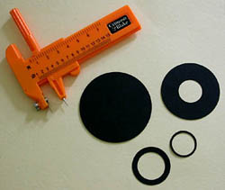
Fig 3. The Crimson and Blake circular cutter.
I used my first stage for about a week or so and found it useful enough to take it one step further and made an improved version with calibration. Fig 4. shows polarizer and analyser with lines which line up with similar markings on the scope [standard notation for the optical vibrational axis of polarization E-W polarizer N-S analyser]. The new stage is now heavier being made from high quality plastic with 0-360 degrees marked off in 5 degree intervals, it has a better bearing and a spring slide clip. Also shown are retardation plates made from cellophane and mica which give first order yellow and second order blue colours on a birefringence chart but note this depends on their thickness. You can just see my reference lines for correct line up of the cellophane and mica samples held within the card mount at 45 degrees.
Note. Retardation plates, also known as accessory plates, are discussed in detail under polarized light compensators on the Molecular Expressions website and they can explain the terminology far better than I can!
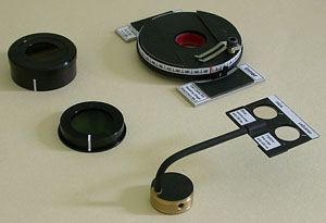
Fig 4.
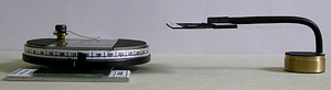
Fig 4. Shows the improved
version of the circular stage and home made retardation plates.
Note that an eyepiece analyser
can sometimes be removed from its mount, try unscrew the locking
ring [if it has one] holding the polaroid disk in place, remove the polaroid
disk and try offering it up to the bottom of a Leitz or Zeiss eyepiece
which on mine have threads at the base. The locking ring used on the original
mount was the same thread as used on my eyepieces. This removes the problem
when I wished to take photos under crossed-polars on my Nikon 4500 digicam
which has an adapter which fits directly to the top of the eyepiece.
Simple and effective retardation plates can be made from cellophane which in my case came from the packing for a set of envelopes, [but note that some plastics will not work] and mica sheet, this can be more difficult to source but small pieces ideal for this type of work used to be found in domestic appliances as part of the insulation assembly for transistor, rectifier and voltage regulator heatsinks. Alas modern methods use a high thermal transfer plastic material but older equipment might have some. I sourced my bits of mica which were just the right size and without alteration from an early 1980's cassette deck!
A note of caution must be added here since mica easily fractures into tiny splinters and can be an irritant if it gets into the skin, also if you are not familiar with electrical or electronic circuits and circuit boards leave well alone and stay with safer materials.
Some of the micas can be too thick and give almost no colours but mine gives a beautiful blue with a retardation figure of around 650 nanometres [650 nm], the cellophane a brilliant yellow-orange of around 400-450 nm. If you are lucky you may be able to see fine lines across the surface of cellophane with a good 10x hand lens, this can be a very useful diagnostic because it's a guide to the optical properties it might have under crossed-polars. If you orientate a sample of the material with the fine lines initially at 45 degrees with respect to your crossed-polars this could give one of its maximum colour depth positions, at least it does on my sample. Retardation or accessory plates are useful for diagnostic purposes when studying thin rock sections under the microscope by adding to or subtracting from the maximum birefingence depending on the orientation of the retardation plates and the crystal under view.
Note. The position of the home made retardation plate in Fig 5. It's not in a plane of focus for the microscope so imperfections in the mica and cellophane are not seen.
Shown below in Fig 5. is the circular stage with an OU thin rock section slide in situ and retardation plate sitting beneath the objective on my scope. The exact positioning of the retardation plate on the stage I have found is not too critical having first got the orientation of the cellophane and mica correct in the mounts. The optical vibrational axis of the mica and cellophane should be at 45 degrees with respect to the polarizer and analyser this should give the maximum colour effect, you can check how effective your test plates might be and the colour depth by first using a sample of your intended material and rotating it on the circular stage under crossed-polars, you will notice as you rotate the mica or cellophane sample the colour will rise from extinction [ideally black] to its maximum colour depth as follows for my cellophane sample:
First rotate a small sample [usually best to sit it temporarily on a slide] for an extinction point with the stage set at 000 degrees, now:
000, 090, 180, 270 degrees will give extinction [ideally a black background but may be very dark grey or brown] if you have your polarizer and analyser properly aligned.
045, 135, 225, 315 degrees will give maximum colour depth of yellow.
More interestingly when I add a full wave plate sometimes referred to as a gypsum plate, [these are calibrated plates with defined optical characteristics] into the light path at 45 degrees to the polarizer analyser and do the same test, the following happens:
045 and 225 degrees, pale pink, the combined effect of the wave plate and sample has added or technically the optical path difference [OPD] of the two has added, on a birefingence chart the full wave plate has an OPD of around 550 nm [pink] and my sample of cellophane 400 nm giving a total 950 nm......second order pink on a birefringence chart.
135 and 315 degrees, grey, the combined effect of the two plates has subtracted, 550 nm minus 400 nm giving a total of 150 nm, a first order light blue-grey colour.
When the effect of the wave plate or compensation plates is additive to the birefringence of a mineral it is normally termed its 'slow' vibration axis and this is usually engraved onto commercially available test plates as arrow markings, mechanically the wave plates themselves always fit into polarizing microscopes in a definite relationship with the vibrational axis of the polarizers normally as a slot cut into the microscope tube at 45 degrees to the polarizers .
You can also try the above experiment with a fixed piece of cellophane like my test plate sitting under the objective in Fig 4. and use the same material on the rotating stage.... see what happens, also try stacking several small pieces of cellophane adding one at a time, providing you keep the alignment the same throughout you will quickly climb up several colours in the spectrum of the birefringence chart, what those colours will be will depend on the optical properties of your particular samples!
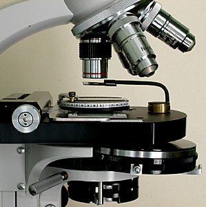
Fig 5.
A note on using objectives. Standard achromats are normally fairly good for simple polarizing techniques and are likely to have better extinction under crossed-polars than apochromatics and because of their greater working distance allow more experimentation with home built accessories. Older apochromatics and fluorites can cause problems as far as extinction is concerned due to complexity of their construction, the tight mounts, type of glass and close proximity of elements all lead to the possibility of poorer results. Modern infinity corrected apochromats may be better in this respect.
With my experiments one of the main problem areas in poor extinction under crossed-polars is the angled monocular and binocular tubes with their associated prisms, swapping objectives and eyepieces made little difference in extinction quality but changing to a simple vertical tube can improve a dull grey or brown or patterned background to black, this can be a useful improvement when taking photos. The quality of the polarizing material is also critical (preferably the Polaroid® HN22 high extinction grade), and the polarizer and analyser should ideally be a matched set, although good results on my brother's Russian Biolam microscope with polarizers cut from an old pair of sun glasses show this does not always apply!
Fig 6. shows the line up of calibration markings for E-W orientation of the polarizer in the filter tray when swung into the normal position. If there are no markings on the polarizer, which is probably the case, you can use crystals of a mineral like biotite [one of the mica family] to align the polarizer. Rotate the crystals under plane polarised light [no analyser in the light path] so that the long crystals face east-west, cross-hairs in the eyepiece can be useful for this, now rotate your polarizer in its tray until the crystals appear darkest, normally a deep brown. Swing out the polarizer making sure it doesn't move in the filter tray and mark off with a pencil both the filter tray and analyzer, you can now make a more permanent marking like below.
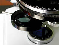
Fig 6.
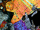
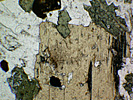
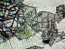
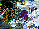
Shown below are typical images captured on the Nikon 4500 digicam of minerals in the OU S260 thin rock sections using the above set-up, all using the 4x objective.
Conclusion.
I have enjoyed experimenting with stages, retardation plates and polarizers etc. and have learnt a lot more about polarizing microscopy than going straight out and buying a dedicated polarizing microscope. You can take this to any level from just cutting pieces of cellophane and polaroid sheet with a pair of scissors and rotating by hand under your scope to see what happens, or if you are lucky enough and have all the right tools you can make high quality custom made parts.... I've taken the middle road. With the improved stage and my retardation plates I've done some quality work on the thin rock samples writing up a full set of printed notes, with photos, on identifying some of the minerals and crystals I've seen.
The question remains though,
is a dedicated polarizing scope worth the extra investment in terms of
better results and convenience?
Using the JNOEC polarizing microscope XPT-7 [Brunel SP-70].
There are only a few polarizing microscopes in the UK at an amateur price level but one possibility is the Chinese made XPT-7 known in the UK as the Brunel SP-70.
Note. With reservations about Chinese microscopes, Brunel allowed me to test one of these on a sale or return basis, I subsequently bought it and have no connection with Brunel Microscopes directly or indirectly, these are my comments for anyone who is considering buying one.
The logo stamped on the microscope's model / serial number plate corresponds to the logo of JNOEC [Jiangnan Optics & Electronics Company] who name and display the model XPT-7 as part of their range. The company's web site 'About Us' page, states that JNOEC was 'founded in 1943' and was 'one of the earliest optical enterprises in China'. They note that the companies it has collaborated with include Leica [U.S.A.] and Nikon [Japan].
There are other mid-priced polarizing microscopes on the market but many of them are variations on the biological microscope with polarizer and analyser added. The basic layout of the XPT-7 is shown in Fig 7. with text overlays.
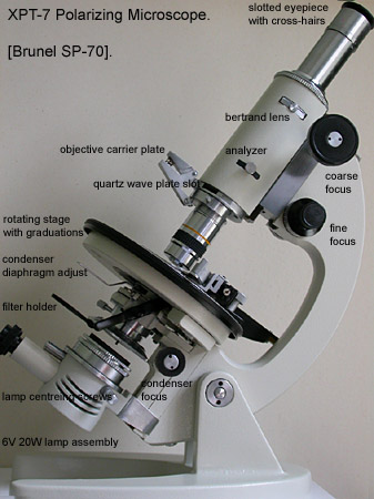
Fig 7. XPT-7 SP-70
Polarizing microscope.
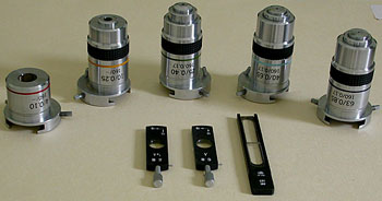
Fig 8. Five strain-free
achromats in their dedicated mounting plates come with the
scope plus quarter and full
lambda waveplates and quartz wedge.
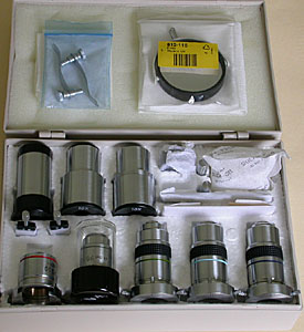
Fig 7. The Mechanics.Fig 9. The accessories case which comes with the scope houses a 5x eyepiece with cross-hairs [focusable], two 10x widefield eyepieces with option of fitting a grid or cross-hairs, centering adjusters for the objectives, mirror, slide clips, wave plates and stage micrometer. Some of the bags are my own. In the empty slots left by the 5x eyepiece and 10x objective which are on the scope I've added a 6.3x Leitz eyepiece [black, top left] and cased Leitz 100x objective. The small empty slot is for the supplied small blue filter, again on the scope. The stage micrometer has a resolution to 0.01 mm and is made to a good standard.
Fig. 7 shows the basic layout. There is a lot I like about this scope, one of them is the optical path from the simple plug-in variable halogen light source through the Abbe condenser with its swing-out top element to the straight tube and eyepiece, removing prisms from the light path; a design tried and trusted from the Victorian era! The base is heavy enough to swing the whole limb assembly horizontal without problem and the single 'clip-in' objective carrier keeps the mechanics simple and price reasonable.
Paintwork and finish is acceptable with some paint chips and rough spots but the overall look is pleasing and balanced. The mechanical engineering I would describe as 'honest engineering' with minimum fuss, however on this example everything works OK with coarse and fine focus firm, but having reasonable 'feel', only using 63x did I notice a slight 'dead-spot' in the fine focus. The nicely weighted 130 mm diameter circular stage rotates freely and is a joy to use; good calibrations with vernier and friction lock together with mounting holes to accept a universal mechanical stage complete this part of the scope. [I've temporarily fitted a Russian Biolam mechanical slide carrier].
There is no field diaphragm which I thought could cause problems with contrast using 40x and above objectives, however tests with field stops show there is no significant improvement in contrast when tested at 40x, I oiled up the Leitz 100x and it gave a bright, high definition image. The condenser diaphragm is open to dust which I'm not too happy with but the condenser itself works well and the adjustment arm works smoothly.
The wave plates with direction markings all fit snugly in their mounts and the Bertrand lens, normally out of the light path has centering screws showing attention to detail. There is a knurled ring above it which controls the Bertrand lens iris diaphragm. The polarizer in its dedicated holder just above the light filter has graduations and locking screw for accurate alignment and the lamp assembly has centering screws. The eyepiece tube has two cut-outs allowing the cross-hair eyepieces to be shifted from the normal N-S E-W to the 45 degree position. The eyepiece optics themselves are not coated but I didn't detect any reflections or contrast problems and I particularly like the performance of the 5x. Alignment of the cross-hairs on the 5x eyepiece is good but I fine tweaked it by slackening the 3 tiny screws holding the cross-hair ring in place and moving it a couple of degrees. Finally the condenser runs on a plastic rack-and-pinion mechanism but is so light that there should be little stress on parts, it has a smooth action with no back-lash.
Fig 8. The Objectives.
4x NA 0.1 is OK, however as with many cheaper 4x objectives, it's spoilt by marked curvature of field, especially if used with the 10x wide-field eyepieces. However I do not like wide-field eyepieces [they remained in the accessory case throughout most of my tests] and with the 5x eyepiece it's acceptable at least for use as a 'scanning objective'.
10x NA 0.25, this is the 'gem' of the collection in my opinion, not only does it give a sharp contrasty image with resolution nearly as good as my Zeiss 10x planapo but has a good flat field using the 5x eyepiece and none of the very close working distance problems of the Zeiss. Tests with special stained histology sections and OU S260 rock sections shows a highly pleasing image and so far is the most used of the group.
20x NA 0.4, 40x NA 0.65, 63x NA 0.85, these are all competent achromatics; results with my Klaus Kemp diatom test slides and strews show results comparable to others I've seen in their class including the Russian Biolam pre DIN range, previously owned Russian DIN objectives and a Zeiss 40x achromat. The 40x and 63x have sprung front mounts.
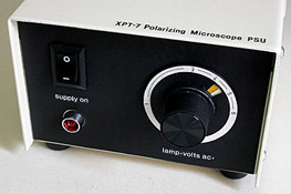
Fig 10. The Power Supply.
As received this comes without a marked fascia and no power light. I've added a neon mains indicator, new fascia plate and text overlays, made a custom knob with calibrated markings for the lamp volts with different coloured zones for quick setting. Internally there is a small printed circuit board with a triac to alter the volts arriving at the primary of the transformer via the front panel control [similar in principle to a light dimmer]. The unit runs cool even after long periods and the light has always been stable. At this point I should mention the quality of the light which has a good white balance at around 3.5-4 volts especially if you fit a better quality filter and don't use the one which comes with the unit. I made a 'doublet' consisting of an IR filter bonded together with a very good quality blue filter [both 32 mm] which fit snugly on the slight recess on the top of the lamp, this can be seen in Fig 7. as a thin 'black strip' sitting on the lamp. The lamp is in a centering mount.
Obtaining a good white balance at reduced voltage should ensure long life of the bulb, the filament is not a special flat wound type but this is not important since a ground glass element is placed directly above the bulb and is a useful guide for adjusting the condenser since there is no field diaphragm to focus on. I focus on the ground glass and then focus the condenser down slightly, I've checked this against some temporary field stops I made and the optimum position of the condenser seems to coincide with both methods.
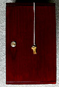
Conclusion.Fig 10. The modified power unit and the case supplied which comes with internal rails for the accessories tray and secure clamping screw for transport. The fit and finish of the case was rather basic so I strengthened the internal shelf supports with pva glue, sanded down the woodwork and applied a darker mahogany stain inside and out.
After spending a considerable amount of time on this scope, I like it, I've tested it on many slides with the 5x eyepiece [you've guessed, I don't like the 10x eyepieces] and my Leitz 6.3x Periplan which corrects nicely for the high power objectives, it gives good results under bright field and polarized light and like the Russian Biolam range [not officially imported into the UK any more], all the key components are adjustable with simple tools which makes any future maintenance easy or modifications possible.
I think the key point in favour of this scope over second-hand polarizing scopes or others I've seen on the market is the completeness of the package. If you like doing a lot of polarizing work and want to take it one step further than adding polarizers and analysers to your existing scope it is hard to beat in its price bracket.
Click here for a second page showing some of the results in the form of a photo gallery.
Comments to the author, Ian Walker, are welcomed.
© Microscopy UK or
their contributors.
Published in the June
2003 edition of Micscape Magazine.
Please report any Web problems or offer general comments to the Micscape Editor.
Micscape is the on-line monthly magazine of the Microscopy UK website at http://www.microscopy-uk.org.uk with mirror site at http://www.microscopy-uk.net.