If you have a black and white video camera for microscopy it may have a significant sensitivity to near infra-red light. This can be exploited for simple near infra-red microscopy by using a near IR light emitting diode for the light source.
The author's first venture into transmitted near IR microscopy is simply described below and inspired by Tony Dutton's reports (see Acknowledgements and Refs.). I was quite intrigued by the results and hope this article will encourage others to try it.
Near infra-red microscopy has potential benefits for capturing images of insect parts and other subjects such as tiny shells, horn and some minerals which in visible light are almost opaque. A bonus is that a significant increase in depth of field is achieved with IR (typically a 70% improvement) which is especially useful for the 'thicker' subjects which benefit from this type of lighting.
The blue hypertext links to the more technical aspects in an Appendix.
Many amateur microscopists use a black and white camera for video microscopy as they are relatively inexpensive and offer good resolution. The typical CCD sensor in the modern solid state B&W camera has a significant sensitivity to infra-red (more correctly near infrared), especially if designed for low light or night-time surveillance use. For visible light video microscopy this sensitivity is detrimental and an IR filter is essential to cut out the IR component emitted by a microscope lamp.
However, this IR sensitivity can also be exploited for video microscopy by using an inexpensive IR light emitting diode (LED) as the light source. The eye isn't sensitive to IR so a TV monitor connected to the camera is used for visual studies with images stored as stills/video on a PC or video recorder. The LED's are available for less than a pound (or a few dollars) from electronic hobby shops.
What do you need?
- Compound microscope (the subjects described below are best viewed at low power i.e. 3x-10x objectives.)
- Black and white video camera without a lens (they usually have a so-called 'C' mount). Note that the camera must be a security type with a removable lens. A domestic colour camcorder will not work because they have IR filters. (Note added Sept. 2000. Some camcorders and digital stills cameras now have a 'night mode' where the IR sensitivity of the sensor is exploited. Maybe these also work if attached to a microscope to capture IR microscopy images. I'd be interested to hear of readers who have experience of this).
- Infra-red light emitting diode (See sources).
How do I know if my black and white camera is sensitive to IR light.
Point a remote controller for a TV or video recorder straight at the video camera with the camera hooked up to a monitor. If you get bright flashes from the remote controller when you press the buttons it should work for IR microscopy. If you don't, it may mean the camera is designed for visible light use only and has an IR filter incorporated on the CCD sensor which cannot be removed. (Some cameras have the IR filter on the 'C' mount lens hence try again with the lens off).
Preparing the IR light source
 Most of the IR emitting LED's can be powered
from a single 1.5V battery. From the LED's stated
specifications a simple circuit can be devised to drive the
LED correctly (ask a friend with electronics knowledge if
unsure). The LED should have a suitable resistor in series to
drop the current to that recommended. I used a variable
resistor (available from hobby shops) which acted as a lamp
dimmer. Thanks to a
reader, who suggested it is advisable to have a 100 ohm
resistor in series with the variable resistor so that the LED
is protected when the variable resistor is set to zero.
Most of the IR emitting LED's can be powered
from a single 1.5V battery. From the LED's stated
specifications a simple circuit can be devised to drive the
LED correctly (ask a friend with electronics knowledge if
unsure). The LED should have a suitable resistor in series to
drop the current to that recommended. I used a variable
resistor (available from hobby shops) which acted as a lamp
dimmer. Thanks to a
reader, who suggested it is advisable to have a 100 ohm
resistor in series with the variable resistor so that the LED
is protected when the variable resistor is set to zero.
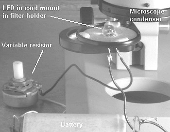
The crude (but effective!) set-up I used for simple trials is shown right. I've simply friction fitted the LED in the centre of a piece of card that fits the condenser filter holder and the card is held in place with 'Blu-Tak'. (The filter holder with LED would of course be swung in for microscopy).
If you don't have a condenser, the LED can probably be mounted somehow in the optical axis below the microscope with the LED 'lens' pointing upwards. Some of the LED's have quite wide beam angles so a condenser may not be necessary for even lighting.
Preparing the video camera
Mount the video camera in the way you normally would on the microscope without a video camera lens. I do all my studies with the camera directly mounted into the eyepiece tube with an adaptor, some prefer to use with an eyepiece and an appropriate adaptor or camera support. All adjustments to the lighting, microscope and camera have to be carried out by inspecting the image on a TV/video monitor (or a PC image capture board may give a good enough preview image to use).
 Centring the LED
Put a slide on the stage and focus with a low power
objective on the subject using the available IR light. (This
is to first ensure the objective is focused).
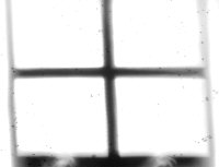
Move the subject out of the field of view and inspect the light quality on the monitor. The LED's are quite small and may not be centred properly or the LED aligned quite vertically, so a bit of adjustment may be needed (this is easier if you have a centring condenser). If a condenser is being used, check the centring by racking down the condenser so the LED comes into focus. The high power LED I used had a four segmented array (shown right above). After centring, rack the condenser back up towards the slide to obtain an even light field. I was quite surprised how even a light was achieved from such a small source (for my LED the black cross was invisible after refocusing the condenser).
What subjects to try
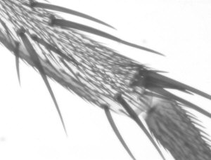
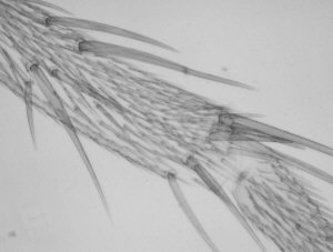
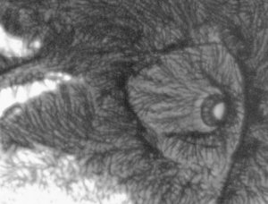
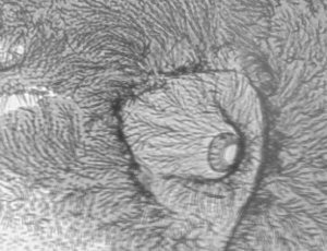
It's best to start with prepared microscope slides. If you have a selection pick some which have some detail that is very dense i.e. almost opaque to visible light that in IR light may be more transparent.The present author tried a selection of subjects including those demonstrated and reported by Tony Dutton (ref.1, and asterisked below) e.g. chitin of insect parts, horn etc. Subjects that may work well are:
- insect bodies which are almost opaque in visible light *
- insect legs or jaws with semi-opaque features *
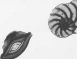
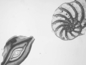
- semi-opaque shells e.g. foraminifera
- some minerals e.g. biotite *
- horn sections *
- most exciting of all is live subjects, e.g. where the IR may penetrate the exoskeleton of live insects, aquatic larvae to reveal internal features in motion (I've no experience of this area yet, let me know if you have tried this).
(Out of interest I have tried a variety of prepared subjects e.g. stained botanical specimens, histology to see if IR lighting offered any benefits. I obtained pale ghostly images for most of them as perhaps expected, let me know of other subjects that may benefit).
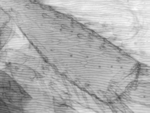
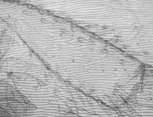
Comparison of video stills taken in IR and visible light
In the table below I have shown pairs of video stills captured for subjects taken in both IR light and visible light. The IR images were captured using the set-up described above. For visible light I used the same video camera with a 240V / 75W tungsten photo-enlarger lamp with an IR filter (available from photo-outlets) in front to cut out the IR component emitted by the lamp.
I wasn't too sure how to compare the images fairly, so have presented a selection of unretouched images and some post processed if the originals were too 'flat' (low contrast) or too dark. Compare the images more in terms of the relative detail conveyed and the depth of field as post capture brightness and contrast adjustments will often be carried out to obtain pleasing results without losing detail.