|
by Ted Clarke, USA |
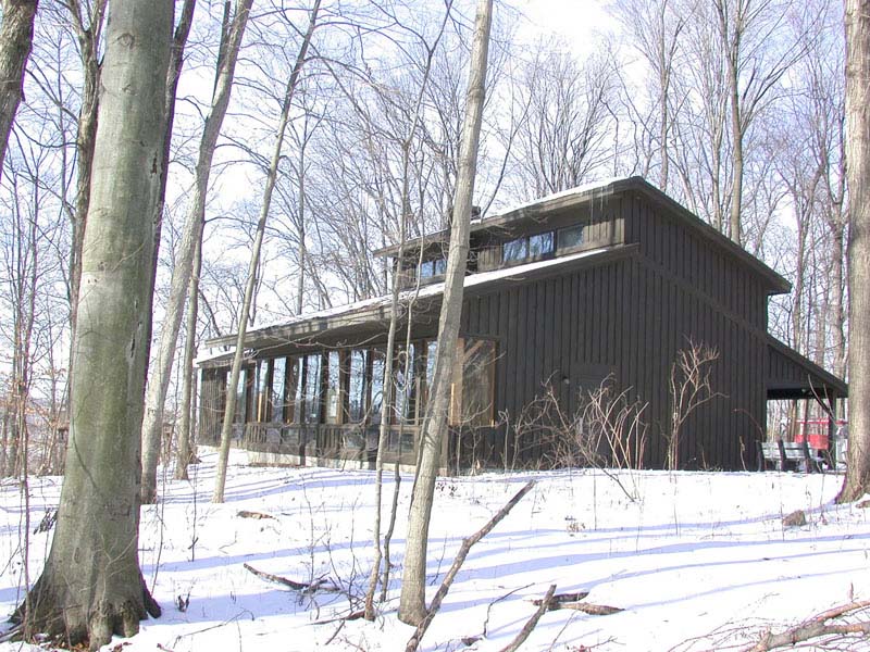
Fig. 1 |
|
by Ted Clarke, USA |
Fig. 1 |
Please click on each image to view a larger version.
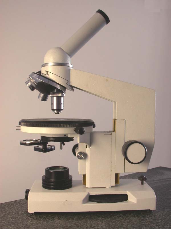
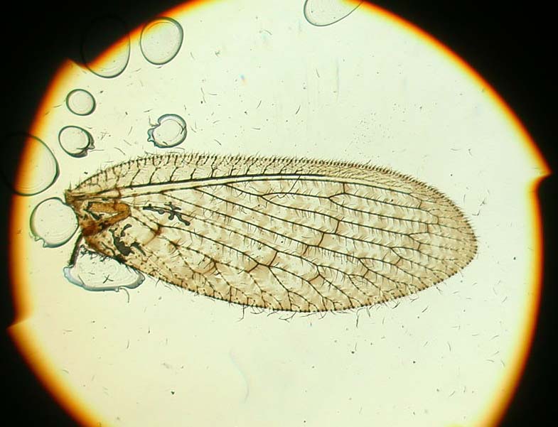
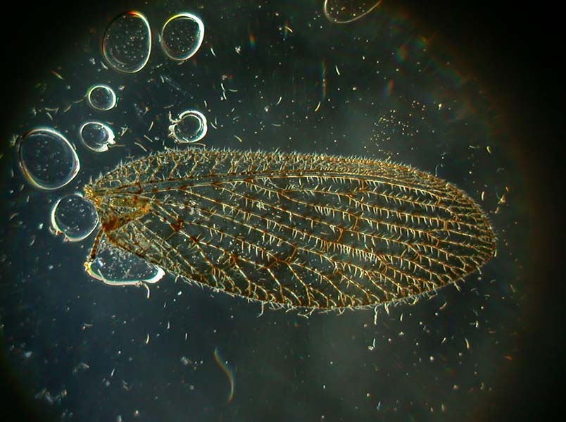
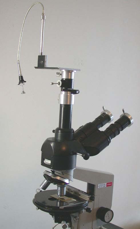
The Maple Wood Nature Center of LaGrange County Indiana uses a polarized light model of the LOMO America Multiscope (Biolam Student Microscope) for teaching natural science to classes of young people. The nature center is shown in Figure 1. Figure 2 shows their Multiscope. I made two darkfield inserts that fit in the filter holder of the 1.25 NA Abbe condenser shown in Figure 3. The smaller diameter stop is used for darkfield with the 4X 0.15 NA and 9X 0.25 objectives. The larger stop shown in the filter holder is for darkfield illumination with the 40X 0.65 NA objective. The object of this article is to demonstrate the typical imaging performance of this microscope when used for teaching the classes. This means the condenser is in the all-the-way-up position and the aperture diaphragm is left fully open. The Nature Center does not use a color correction filter with the 30-watt tungsten filament built-in illumination through a diffuser in the microscope base. The specimen chosen for this article is a mounted insect wing 9 mm long. This specimen was chosen because the transparent wing is covered with hair patterns that were found by the naturalist, Scott Beam, to be a good sample for comparing darkfield illumination with conventional brightfield illumination. Two different methods for constructing darkfield stops will be given later. Previous articles in Micscape have described my own modified Biolam (Multiscope) microscope. My own system was first used to record the entire wing in both brightfield and darkfield using Koehler-Clarke illumination. The coarser hair pattern linked to the wing veins is visible in both the brightfield and darkfield images shown in Figures 4 & 5, which also show the imaged field diaphragm. The use of an 80A color correction filter in the illumination system results in the white background of Figure 4 without the need to reset the white balance in the Coolpix995 used to record these and the subsequent images. An additional photomicrograph, Figure 6, was made with the 4X 0.15 NA LOMO objective and Koehler-Clarke illumination for later comparison with the equivalent image from the Nature Center microscope.
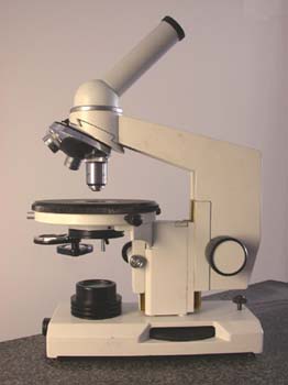
Fig. 2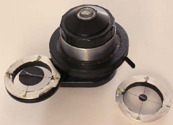
Fig. 3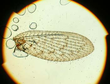
Fig. 4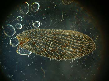
Fig. 5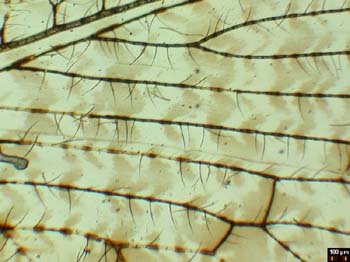
Fig. 6
Fig. 7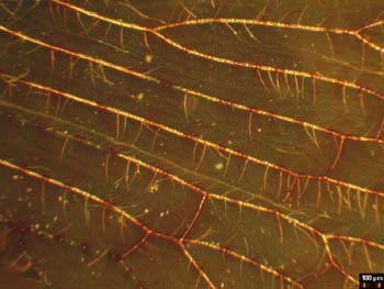
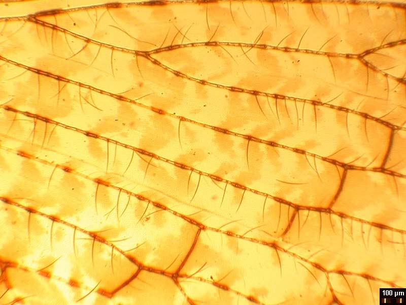
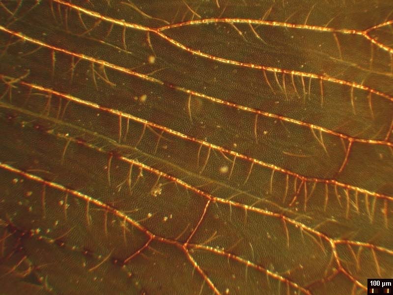
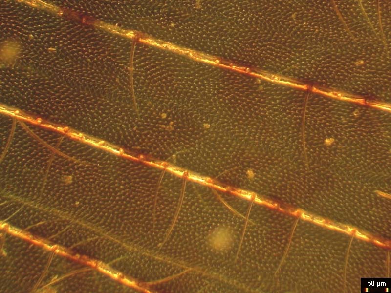
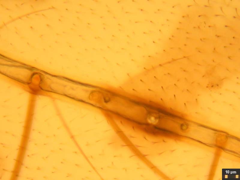
Fig. 8Figures 7-12 a sequence of brightfield and darkfield photomicrographs of the same field on the insect wing specimen recorded using the Nature Centers Multiscope. The swing lens shown below the condenser in Figure 3 was used with the 4X objective to obtain more even illumination of the field, which is its intended purpose. The smaller of the two stops shown in Figure 3 was used to obtain darkfield illumination for both the 4X and 9X objectives. A comparison of the images indicates that there is a hexagonal array of much smaller hairs on the wing membrane. The presence of this hexagonal array in images taken with the nature centers Multiscope is first apparent in the darkfield image taken with the 4X objective. The brightfield image, Figure 6, recorded with a 4X objective using Koehler-Clarke brightfield illumination also shows evidence of the hexagonal array, but not with as much contrast as the darkfield image of Figure 8. An explanation from the biologists on the effect of the hair arrays on insect wing aerodynamics would be interesting.
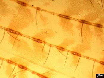
Fig. 9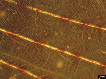
Fig. 10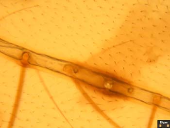
Fig. 11
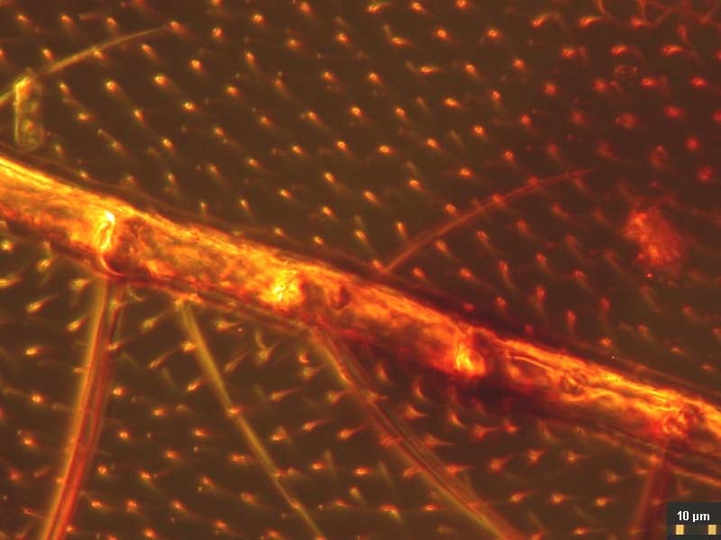
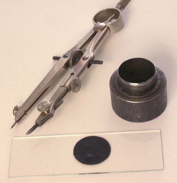
Fig. 12Next I will discuss the design and construction of the darkfield stops. The filter holder of the LOMO condenser is close to the aperture diaphragm, assuring a sharp transition at the inside of the hollow cone of darkfield illumination illustrated in Figure 13. (Figure 13 shows the condenser oiled to the bottom of the slide, which is necessary for use with objectives with a greater NA than 0.75) The condenser height may have to be adjusted somewhat to get the object field at the crossover point for the hollow cone of illumination illustrated in Figure 13. Rings with wire spiders supporting the darkfield stops were machined from aluminum to fit in the filter holder. The rings have thin flanges to aid in insertion and removal. The rings have a flat and a notch in the flange to clear the swing post and stopping post projecting below the condenser. These features also assure repeatable orientation of the stops in case the axis of the filter holder bore is not coincident with the condenser axis. The fine wires for the spiders pass through holes in the ring flange and are locked with dabs of epoxy prior to trimming off the protruding wire ends. Trial stops were cut from paper and slipped between the wires to establish the proper stop sizes for the 9X and 40X objectives. The proper stop size and centering was found by removing the eyepiece and looking at the rear focal plane of the objective with the condenser height properly set and its aperture fully open. The stop can be seen imaged at the back of the objective. Once it is of the correct size a crescent of light should appear when it is moved off center slightly. I have found that a stop diameter between 17.1 and 18.2 mm in diameter will work for the 40X objective. If it is too small, a ring of light will surround it is when centered. This situation could be used to give circular oblique lighting (COL). For COL illumination, the aperture diaphragm should be adjusted so its edges are visible at the outer edge of the bright ring of light seen at the rear of the objective. The paper disks for the trial stops were cut with a drafting compass and a bevel-edged drill stub as a cutting edge in place of the pencil lead point. The brass shim stock disks for the final stops were scribed with the compass, cut out with a scissors, and filed to the scribe line. (The black painted brass disks shown in Figure 3 are just large enough to give good darkfield and are 17.14 and 5.92 mm in diameter.) The compass is shown in Figure 14 along with a simpler design for a stop consisting of a disk of electrician tape cut with the compass and stuck on a clean slide. The paper punch in Figure 14 happened to be the right size to cut the stop from electrician tape. Figure 15 shows this slide-mounted stop fitting in the gap between the filter ring and the bottom of the condenser. This type of stop has to be centered each time it is used, so it is not as suitable for a class room situation. The image quality is the same as with the ring mounted stop as seen in Figure 16. The fine hairs in this image have a better orientation to show their shape than those imaged in Figure 12.
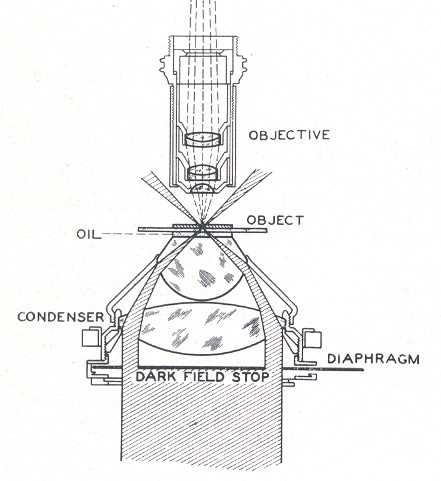
Fig. 13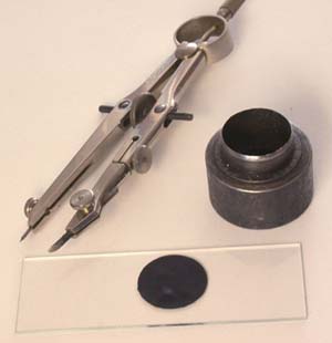
Fig. 14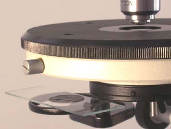
Fig. 15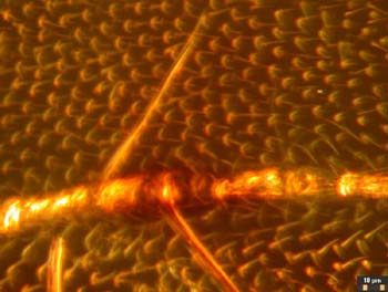
Fig. 16
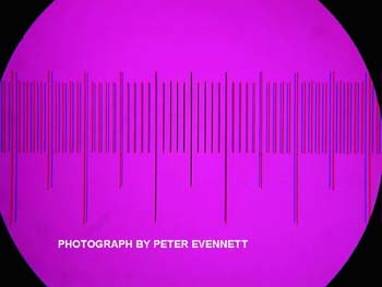
Fig. 17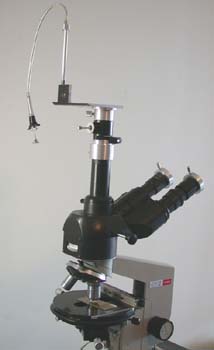
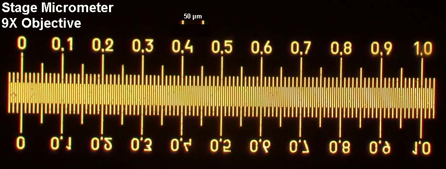
Fig. 18Finally, I will deal with how the images were recorded with a Nikon Coolpix995 (the earlier version of the Coolpix4500). An earlier article by me in Micscape showed the poor image quality that results when a noncompensating relay lens is used in place of a compensating eyepiece to couple a scientific grade digital camera to a Zeiss Universal microscope. This situation applies equally to the LOMO microscopes because the LOMO eyepieces have the same amount of compensation for chromatic difference of magnification (CDM) as do the Zeiss kpl eyepieces of the Zeiss Universal. I tested this again very simply by replacing the LOMO 10X compensating eyepiece with noncompensating 10X eyepiece. I did the comparison using the LOMO stage micrometer as the test specimen and the 9X objective. As expected, the 5 micrometer spacing of the lines was badly blurred towards the ends of the scale. I knew the cause to be lateral chromatic aberration. Peter Evennett provided me a more dramatic example taken with a Nikon MDC adapter connecting a Coolpix camera to his Zeiss microscope requiring kpl eyepieces. Peter used a purple filter to block the green portion of the spectrum. The black lines of his stage micrometer are black in the center of the field and split into pairs of inner blue lines and outer red lines at the ends of the scale. Peters example is shown in Figure 17. None of the adapters currently sold for mounting a Coolpix995 on a microscope have compensation for CDM. A high eyepoint eyepiece with the LOMO CDM compensation was needed to couple the Coolpix995 to the photo-tube of the LOMO trinocular head. This need was met by the high eyepoint LOMO Edupointer 10X eyepiece. This eyepiece adds 22 mm to the system tube length, so using it to replace a viewing eyepiece will result is serious spherical aberration with the 40X and higher power objectives. The LOMO photo-tube for video camera use is short enough that it requires a spacer when used with the Edupointer to become parfocal with the viewing eyepieces. The spacer length required to make the Edupointer in the photo-tube parfocal was determined using the 4X 0.15 NA objective and the LOMO stage micrometer for the test object. The installed coupler gives a total length of 143.6 mm, measured from the locating flange face of the photo-tube to the outer end of the Edupointer eyepiece. The Edupointer eyepiece mounted in the spacer coupling and the camera mount, with cable release, are shown in Figure 18. All of the photomicrographs for this article were taken with the Coolpix lens focus manually set at infinity, the lens aperture set at a maximum, f/2.8, with the lens zoomed just enough for the digital image diagonals to cover the 18 mm FN of the binocular viewing eyepieces. The LOMO stage micrometer was recorded with each of the three LOMO objectives so that scale bars could be constructed and pasted on the images of the insect wing. Figure 19 shows the scale recorded with the 9X objective. The 3.3 megapixel images from the Coolpix995 were resampled to 1.6 megapixels using Adobe PhotoShop and subsequently cropped for this article. These 1.6 megapixel images, if printed in 4X6 inch size, would be expected to meet an Abbe criterion of 500 times the magnification for the 4X and 9X objectives. I have learned to use this strict image resolution requirement, based on the Zeiss literature and subsequent testing for application to photomacrography.
All comments to the author Ted Clarke are welcomed.
Please report any Web problems or offer general comments to the Micscape Editor.
Micscape is the on-line monthly magazine of the Microscopy UK website at Microscopy-UK