|
|
A Gallery of l - Arginine Photomicrographs (using a variety of illumination
techniques) |
|
|
A Gallery of l - Arginine Photomicrographs (using a variety of illumination
techniques) |
L-arginine
is an amino acid present not only in humans, but in all life
forms. It plays a part in the synthesis of proteins on which the
function of all living cells depend.
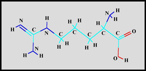
This fairly simple organic molecule
is composed of carbon, hydrogen, nitrogen and oxygen atoms as can be
seen in the structural formula.
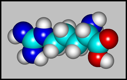
The space-filling model gives a
better idea of what the molecule would look like if we could see
it. (Both images were produced using Hyperchem software.)
Although the melting temperature of
this white crystalline solid is low enough ( 221 degrees Celsius ) to
enable melt specimens to be prepared, I decided instead to use its high
solubility in water to produce crystals by evaporation. A
quantity of the solid was dissolved in several millilitres of cool
distilled water to produce a fairly concentrated solution. A
couple of drops of this solution were placed on a clean slide and the
slide was placed in a cool dust-free location. After all of the
water had evaporated, the slide was checked under the polarizing
microscope to see whether any photogenic structures were present.
If the slide was a good one, it was allowed to dry completely for a
further week and then a drop of the mountant Permount
was placed on the crystal layer and a cover-slip carefully added.
(This final step allows the slide to be kept in pristine condition for
a long period, but it has the side-effect of turning the crystal layer
a pale yellow-orange colour when viewed by normal transmitted
light.)
Note that l-arginine may act as an
eye or respiratory irritant, and should therefore be handled with care.
I must admit that I prefer to
produce melt specimens of compounds because there are fewer variables
that can act to the detriment of the finished product. In
specimens produced by evaporation of the solvent, the
concentration of the solution is of critical importance. If the
solution is too concentrated, unsightly amorphous lumps of crystal tend
to form. If the solution on the other hand, is too dilute, the
thin crystal layer that forms tends to produce shades-of-gray images
under the polarizing microscope, instead of the colourful forms
desired. Only experimentation will find the ideal
parameters. In the case of l-arginine, a relatively concentrated
solution seemed to work best.
The images in the article were
photographed using a Nikon Coolpix 4500 camera attached to a Leitz
SM-Pol polarizing microscope. Images were produced using several
illumination techniques: transmitted light, dark-ground
illumination, phase contrast and polarized light. Crossed polars
were used in all polarized light images. Compensators, ( lambda
and lambda/4 plates ), were utilized to alter the appearance in some
cases. A 2.5x, 6.3x, 16x or 25x flat-field objective formed the
original image and a 10x Periplan eyepiece projected the image to the
camera lens.
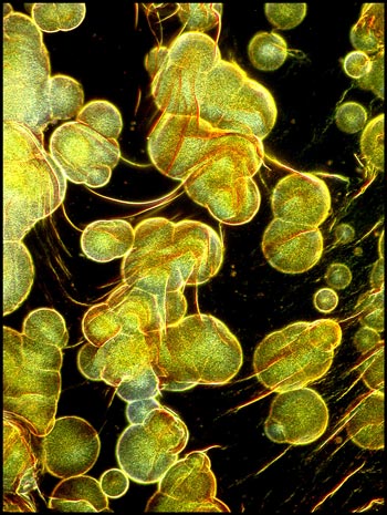
The image to the left below shows a
field near the edge of the cover-slip illuminated with transmitted
light. On the right is the same field using polarized light. It
is interesting that much of the material visible in the left image does
not appear in the right image. This material is referred to as isotropic since
light travels through it at the same velocity in all directions. Anisotropic
material, (which forms each circle in the right hand image) is referred
to as birefringent
because it splits the light rays into two sub-rays which travel through
the material at different velocities. This phenomenon (which
depends upon the packing of the molecules in the crystal) results in
the material being visible between crossed polars.
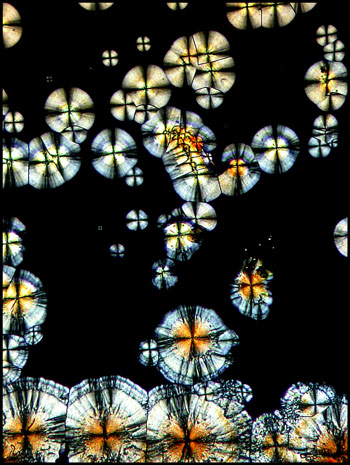
The image to the left below shows
an area near the centre of the cover-slip, where crystal growth has
begun at a large number of sites which are close to one another.
The circular growth fronts have run into one another producing the
strange black intersection lines that can be seen in the higher
magnification image on the right.
Under still higher magnification,
the detail in the circular structures can be seen more clearly.

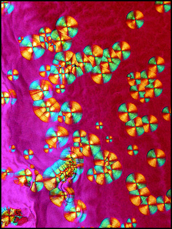
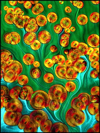
Compensators can be used to alter
the appearance of anisotropic crystals by slowing the velocity of one
of the sub-rays travelling through the material. In the example
on the right below, a lambda/4 compensator was used beneath the crystal
field and a lambda compensator was positioned above. This results
in the brilliantly coloured circles and background.
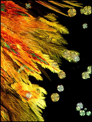
At other locations, (usually near
the edge of the cover-slip), different crystal formations sometimes
occur. The feather-like structures below are illuminated by
polarized light with no compensators (on the left), and with the
addition of a single lambda compensator (on the right).
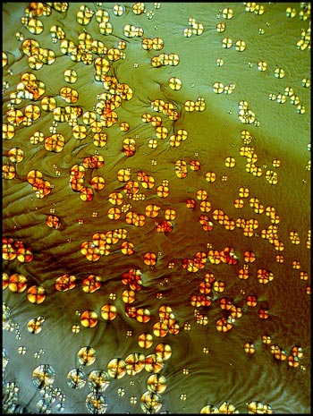
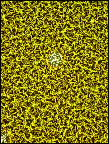
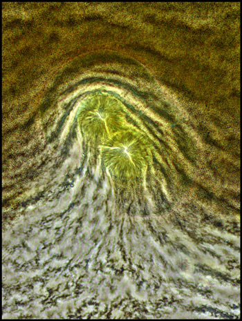
A low power image of a field
between crossed polars, and with a lambda/4 compensator, shows strange
wave-like areas between the circular forms.
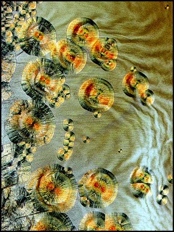
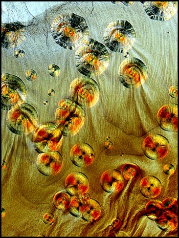
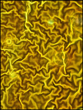
The two higher magnification images
below show the waves more clearly.
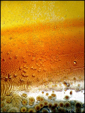
Sections of the slide near the
cover-slip edge sometimes show flow patterns. These can be seen
in the two images below. The one on the left uses normal
transmitted light illumination, while the one on the right uses
polarized light with crossed polars and two compensators (lambda/4 and
lambda).
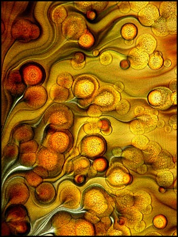
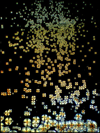
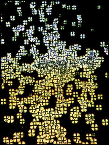
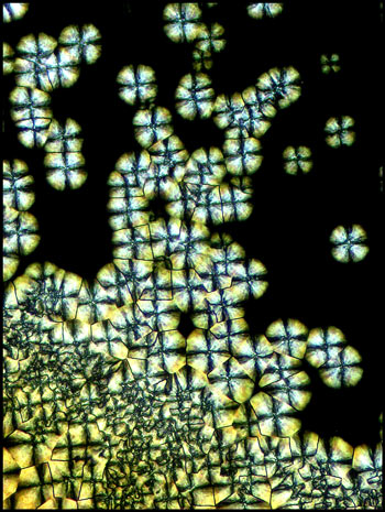
Large areas of one slide
preparation displayed the structures shown in the three images
below. These patterns appear almost fractal in nature.
The black and white image uses dark-ground illumination while the other
two use normal transmitted light.

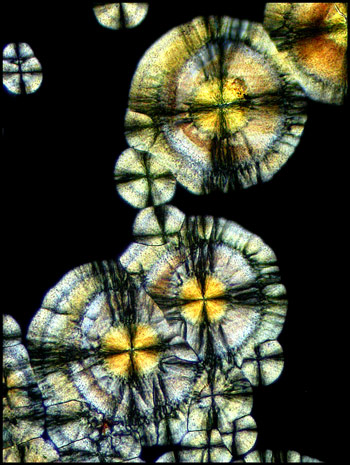
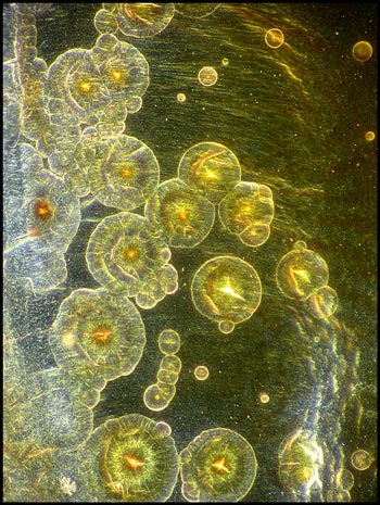
The image on the left below uses
dark-ground illumination. The higher magnification image on the
right, of another location, uses phase-contrast illumination to
distinguish finer structural details.
This final image shows some rather
amorphous circular structures illuminated with a dark-field condenser.
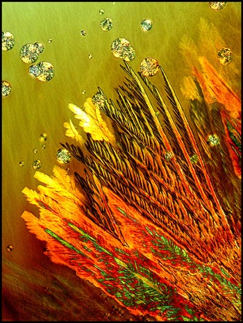
Evaporation specimens, with their
many controlling variables, tend to produce very different results when
several slides are prepared under different conditions. This was
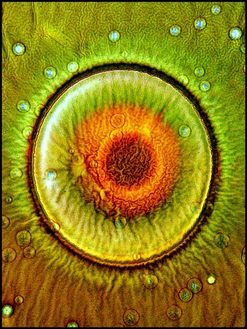
certainly true of l-arginine. My favourite field is shown as the
first image of this article. It reminds me of the false-colour
image of a martian landscape. Images like this one are what make
this hobby so rewarding!
Published in the March
2005 edition of Micscape.
Please report any Web problems or
offer general comments to the Micscape
Editor.
Micscape is the on-line monthly magazine
of the Microscopy UK web
site at Microscopy-UK
© Onview.net Ltd, Microscopy-UK, and all contributors 1995 onwards. All rights reserved. Main site is at www.microscopy-uk.org.uk with full mirror at www.microscopy-uk.net .