 |
| Dealing with the Wild
M20's broken 'gearbox' Plastic gear problems under the stage. By Paul James (UK) |
The plastic gearing which has been in place for perhaps 35-45 years beneath the Wild M20's stage eventually fails....... sooner or later. Since most owners of this beautifully crafted microscope will be aware of its inherent virtues and precision engineering, it might come as a surprise that the close fitting tolerances and ageing lubrication of the under stage multi start thread, which derives its action through the delicate plastic gearing, raises higher frictional forces which are certainly detrimental to the life of the plastic teeth.
| If you are reading this out of interest rather than of necessity and have no problems with these delicate gears it might be prudent to at least reduce the overal friction by applying a low viscosity oil to that particular coarse screw worm beneath and to the rear of the stage : the part that accords transverse motion to the slide. Put some oil also on the two plain bearings that support the plastic gear shaft and the follower as well as the dovetail slide that carries the slide pusher. No harm will come of this despite opinion to the contrary, but this will help to maintain its longevity . Such slowly revolving bearings and screw surfaces hardly warrant the 'ideal' lubrication that manuals advise, so the best solution is to get the viscosity of the lubricant down to very low levels. Dirt has infinitely more abrading qualities than low viscosity oil in this situation. In a nutshell less friction... less strain....... longer living plastic gears. |
Options......Replacement/Adaptation/ etc..
|
The images and ideas expressed in this article should be taken as a guide only. I cannot accept any responsibility for resultant problems arising from reader's endeavours. Please bear in mind that I have just the one defunct stage which I brought back to life again by implementing method 4). I could not therefore fully illustrate the alterations to the control shafting etc which are necessary for the other options. All the options I mention and illustrate are entirely feasible and involve basic metalcraft skills which can be implemented without the use of a lathe, though the latter does help. It is expected that those interested in trying to do the job themselves will be familiar with the process of stage disassembly, as I have not covered this aspect of the work, which is basically self evident in practice. |
My first idea other than replacing the broken plastic gears was to try using rubber belts/bands to transfer motion from one shaft to the other. Once the palstic teeth were turned off the spigot a rubber belt could be installed over the two pulley wheels. Initially it appeared to be the ideal way forward promising a smooth vibration free drive. However there are inherent problems. In order that enough friction is generated for the 'belt' to grip, the tension must be relatively high and so the friction increases in proportion in the plain bearings.
Even if perfect pulleys were machined allowing minimal friction and a more positive uniform motion, the weak link caused by deterioration of the rubber belt(s) was enough to discourage me from wasting time and effort on this method.
If anyone wants to try this and has the facilities to machine the original gear/spigots then face them in a lathe make sure the two pulleys have convex rims so that the centre is highest. Anyone who has experience of drive shafting or bandsaw technology will know this. All band belting rides to the highest point, ensuring in this case that the rubber belt remains dead centre. The other important requirement is that the pulleys be made as wide in diameter as is possible to make them within the confines of that part of the stage to reduce effective rotational friction from the screw shaft bearings. Good Luck !
|
4 Practical options
1) Dislocating Transverse Drive
By dislocating the rear dovetailed slider unit from the screw feed beneath the stage, thus freeing the transverse movement which can be positioned by hand. A very simple remedy which is surprisingly practical and takes only a few minutes to achieve. Whether this suits you needs is entirely a personal matter. The delicacy of motion of this transverse slider is sufficient for all needs. It does have the great advantage of simplicity, and leaves all the control knobs in place without cosmetic compromise of any kind. At least it frees the instrument for use again giving the owner time to think about more sophisticated alternatives if need be.
 |
| Decoupled slider with static multi start threaded shaft and follower out of harm's way. |
2) Direct Drive
A more complex procedure is to extend the feed screw so that it can be manipulated directly from the edge the stage, and so bypass the faulty gear mechanism. This entails a little engineering know how, but can be achieved without use of a lathe. The images show the principle of this. In order that a 'new' control knob can be sited directly on the end of the screw shaft, the two knobs on that side of the stage cannot remain for obvious reasons. Thus the other shaft responsible for fore and aft motion of the stage remains of course but shortened so that it does not project beyong the stage apron and foul the relocated control knob. I DID NOT PURSUE THIS BUT ONLY DEMONSTRATE ITS FEASABILITY. THE DETAILS CONCERNING THE SHORTENING OF THE SECOND SHAFT ARE LEFT TO THE DISCRETION OF THOSE WHO MIGHT LIKE TO TRY THIS. IN A NUTSHELL TRANSVERSE MOTION ONE SIDE : 'FORE AND AFT' THE OTHER.
|
|
 |
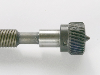
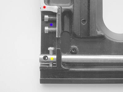
| Typical damaged plastic
gear........when removed reveals taper pinned collar with
polished journal which can be used to support the now yet defunct control knob. The removal of the spigot is not necessary but the pin is proud of the spigot when in place and needs a little grinding down before attempting to secure 'new'control knob |
 |
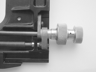
| Control assembly complete
before alterations. Use this Knob for the 'new' traverse control
shown in previous image above. Redundant Teeth can be left alone. Smaller control knob not required and can be unscrewed revealing inner end plate which when unscrewed will allow removal of the 'new' transverse control knob which has to be fitted over the spigot shown below. The gear wheel for the 'fore and aft motion' remains of course. Support plates are an integral part of bearings below. |
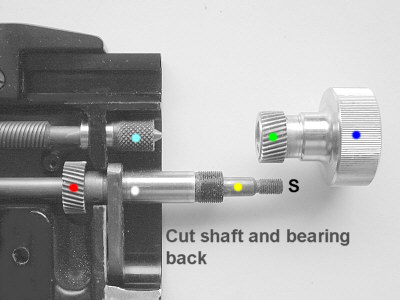 |
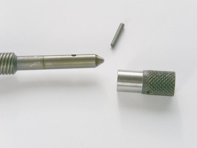
| Redundant knob
can now be fitted to spigot. The bearing and shaft have to be cut back inside the apron of the stage. The shaft must remain proud of the bearing's end for circular spring clip/washer to be fastened stabilising end play |
I strongly advise anyone attempting this to mount the new transverse knob temporarily by covering the spigot with PVC tape so it provides enough friction when pushed on. Any other modifications which come to mind when using the new setup can be considered before more permanent methods of attaching them are attempted.
The resulting layout of control divides the 'transverse' and 'fore and aft' motions to each side of the stage respectively. This may not be entirely convenient to some observers BUT it has the distinct advantage of reliability and simplicity in use with a little more delicacy of control than method 1).
THIS IS A ONE WAY SOLUTION INVOLVING THE CUTTING OF SHAFTS ETC., SO THIS METHOD NEEDS 100% MENTAL COMMITTMENT BEFORE STARTING !!??!!
3) A'foreign' stage
A different stage for the purpose must satisfy several requirements especially stage height, condenser 'elbow room' and of course the actual mount holes. A 'marriage' plate will probably be needed so combining both stage and the fork supporting this. I have a Zeiss unit which is very similar to the M20's stage BUT although fitting wouldn't have been too difficult, it did not allow the full elevation of the M20's condensers. A great pity as it would have looked a genuine part of the M20. There are so many different stages that no unified line of advice or methodology can be given for obvious reasons.
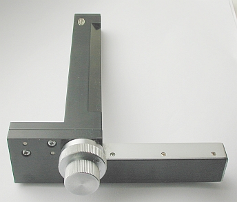
4) An 'add on'Mechanical Stage
A Mechanical slider pusher unit can be adapted too, but much depends on its shape, dimensions, and the complexity of attachment. I eventually ended up using an Olympus slide unit as shown below. The time spent thinking and deliberating as well as doing the job was considerable.........it was more complex than originally envisaged. However it works extremely well, has the same colour and metal finish. Coincidences concerning similar dimensions, and a little luck helped turn this into a reality. The downside is that the unit looks too angular for the M20? That said it does the job efficiently.
 |
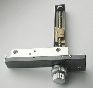 |
The concentrically driven slide mover from Olympus is well made and importantly has a similar finish to the M20 so at least it would merge well with the stand. Mounting is of course the problem. Fortunately with a couple of strokes of good fortune concerning dimensions, this Olympus gadget was ideal even allowing the original slide clamp to be used too, though foreshortened somewhat as can be seen below.
I wanted to accomplish this without changing or altering the original upper stage and so use of existing key apertures etc was adopted. I think the images are self explanatory showing that it can be done without irreparably damaging it.
 |
 |
|
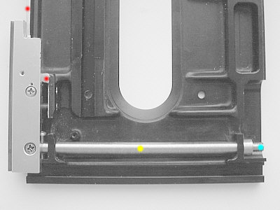
Steel rod with threaded holes to provide holding and stability as well as 2 screws to trap a plate not shown both hold the main angle plate for the mechanical stage. Underside of stage needed a little paring down with a file for ease of alignment. |
Rod utilises original stage apertures and helps also to transfer loads etc. Simple end nut turned circular so as to fit radius therein over threaded end. Angle plate now accurately and positively located. |
 |
 |
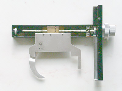
| Original slide holder
shortened and fitted to the Olympus unit. I had to remove the finger stub. Whilst in the mood for change I also clipped short the cross fork which I think is far too long and therefore allows easier slide access. The internal mechanics are excellent. The transverse thread is chromium plated and sports an adjustable follower, ensuring no play for a very long time indeed. |
The finished stage which works extremely well. Marks for solidarity and longevity ...........9/10 :) Marks for cosmetic appearance.............7/10 :(
Total cost ............. £8.50 ! :D |
| All comments welcome by the author Paul James |
Microscopy
UK Front Page
Micscape
Magazine
Article
Library
Please report any Web problems or offer general comments to the Micscape Editor.
Micscape is the on-line monthly magazine of the Microscopy
UK web
site at Microscopy-UK
© Onview.net Ltd, Microscopy-UK, and all contributors 1995 onwards. All rights reserved. Main site is at www.microscopy-uk.org.uk with full mirror at www.microscopy-uk.net .