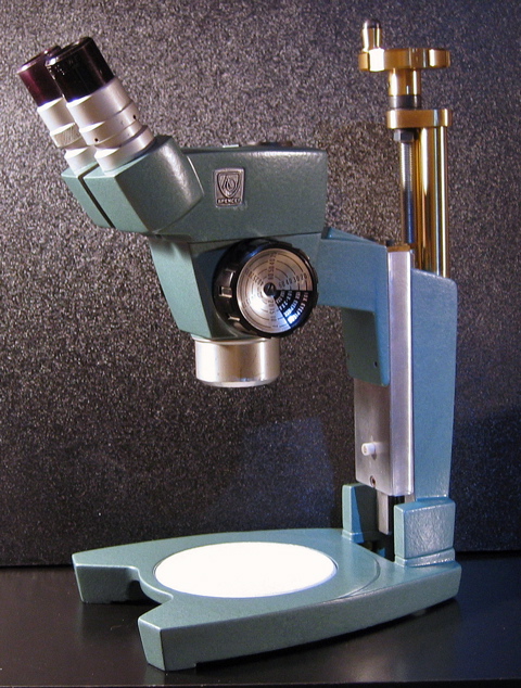
Photo 1 - The fully restored and refinished stereo microscope with a unique focusing mechanism.
|
Restoring an American Optical Cycloptic stereo microscope by Ian MacGregor, Burnaby, BC, Canada |
A retired coin collecting friend of mine needed a stereo microscope for his hobby and was on a limited budget. I had a "junker" American Optical Cycloptic that was given to me so I set about restoring it for him and this was the result ( Photo 1 and 2 ).
Photo 1 - The fully restored and
refinished stereo microscope with a unique focusing mechanism.
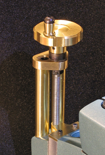
Photo 2 - The focus mechanism uses a lead screw and nut
similar to that found on all metal lathes and milling machines. Machining
a new helical milled pinion was not an option and this design is fine for
hobby use. I used brass because I didn't have any suitable aluminum
pieces in my "short ends" bin and I was not going to purchase new
stock.
The 'scope was in sad shape mechanically but the optics were good ( Photo 3). The base was badly corroded from contact with sea water, the vertical slide was jammed, the teeth of the focus pinion gear were completely stripped, and the spring detent on the magnification changer was broken. In other words, I had a number of interesting technical challenges to overcome without spending too much time or money..... I love solving technical problems and this was going to be fun!
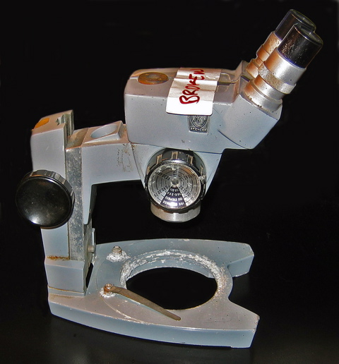
Photo 3 - The "junker" AO Cycloptic that was given to me. Note the
"BROKEN" label on the binocular head.
The following photos ( 4 to 9 ) illustrate some the machining procedures used in the restoration. I welcome all enquiries about specific details for any home shop machinists who are interested.
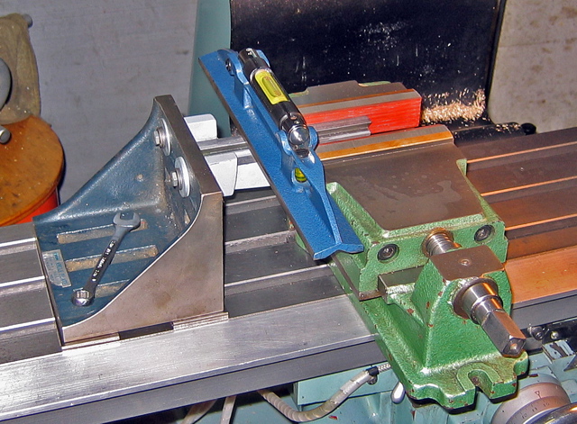
Photo 4 - The milling set-up for machining the hemispherical
groove in the vertical column. The milling vise is fitted with soft
jaw inserts to grip the irregular shaped column. A very sensitive
machinist's level and angle plate were used to ensure that the column was
flat and perpendicular to the milling spindle. Like all my machine
tools, the vertical mill has been accurately levelled in the X and Y axes
and milling table is a flat and level surface.
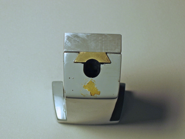
Photo 5 - The column of the scope after the milling
operation. The damaged end of the aluminum slide was milled square
as well as grooved with 1/2 inch diameter ball-nose cutter. Some "
technically challenged " individual had used a steel hammer to free the
jammed slide! This explains why all of the teeth of the pinion gear
were broken.
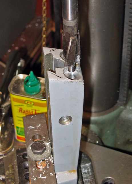
Photo 6 - The top of the column was drilled,
counter-bored and tapped 3/8 - 16 UNC in the drill press to receive the
new 5/8ths inch brass extension pillars.
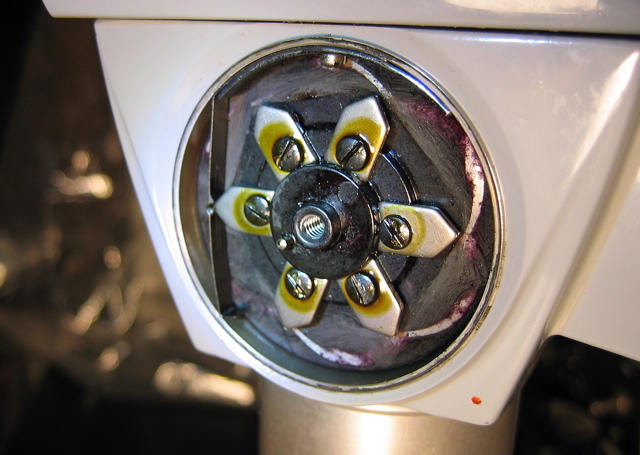
Photo 7 - This illustrates what an unbroken magnification changer detent spring ( on the left-hand side ) SHOULD look like. I borrowed a working Cycloptic for this photo and , of course, to take measurements.
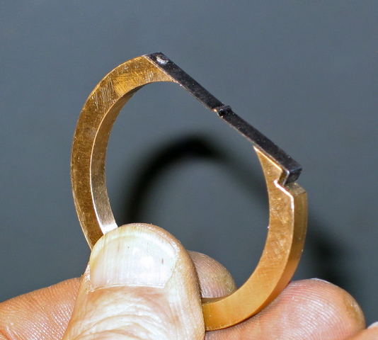
Photo 8 - The repaired detent spring. The broken
spring segment was punched 1/16th inch and riveted to an accurately
machined bronze ring.
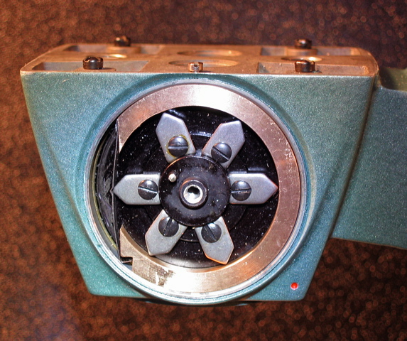
Photo 9 - The repaired spring, in place, and just
prior to optical alignment. Because the C-shaped bronze ring will
deform easily, the tiny 2-56 UNC machine screw fits lightly in a dimple in
the bronze ring and exerts no pressure. The ring is fixed in
position with Loctite 680 and the machine screw was only used as an aid
during the aligning process. The screw was re-cycled from the
original spring assembly.
A previous article explains how I used reverse electrolysis to remove the salt water corrosion on the base. Auto body filler and a hammer-finish enamel completed the job.
All comments to the author Ian MacGregor are welcomed.
Microscopy UK Front Page
Micscape Magazine
Article Library
© Microscopy UK or their contributors.
Please report any Web problems or offer general comments to the Micscape Editor .
Micscape is the on-line monthly magazine of the Microscopy UK website at Microscopy-UK .
© Onview.net Ltd, Microscopy-UK, and all contributors 1995 onwards. All rights reserved. Main site is at www.microscopy-uk.org.uk with full mirror at www.microscopy-uk.net .