 |
 |
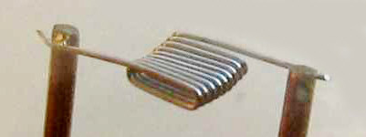
| 8 watt filament spot welded to posts | 15 watt filament spot welded to posts |
| Care of Low Voltage Incandescent
Lamps Helping to ensure your lamphouse's bulb reaches old age By Paul James |
A large proportion of the incandescent light bulbs made specifically for microscopes are expensive items. They are often mounted in centering collars so that they are ready for use immediately after insertion into the lamphouse, assuring their alignment with the microscope's optical axis. If however the power supply unit's output is at variance with the rated requirements of the bulb, then its potentially long life could easily be curtailed to a few hours or seconds. So let's take an elementary peep into this aspect of microscopy which tends to be neglected, simply because many lamphouse structures are 'buried' in the base of the microscope and are therefore 'out of mind'.
The Filament
The bulb's delicate filament is usually fashioned from tungsten simply because that metal has an exceedingly high melting point, so enabling a higher operating temperature than others. With high temperatures comes more light output and usually broader colour bandwidth. But filaments don't like the sudden rise in temperature at the onset of use, which causes rapid expansion and also tends to strain the interfacing weldment where the 2 supports are attached. After many hundreds of cycles of use, either the weldment fails or the filament itself. Though this will occur sooner or later, the trick is to try and prevent its premature failure and with a little thought and care this can be achieved.
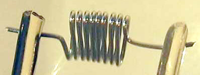
Different flaments can be seen below each supported between posts and its attachment by 'spot welding' on each side.
|
|
| 8 watt filament spot welded to posts | 15 watt filament spot welded to posts |
Its structural integrity and neat gridding together with accurate placement within the bulb's glass envelope is of course vital and partly accounts for its intrinsic higher cost compared with similar domestic lighting units, where the filament's internal position isn't too important. One of the problems that welding 2 different thicknesses of metal is encountered here, and is in part the cause of some premature failure because of differential expansion at the welded joint when the current is switched on and off. In a domestic bulb the filament's stability of position is not important so the feed posts are not as stout as shown here, and so the rapid expansion differential isn't such a problem. In microscopy the illumination source's location must ideally be stable to provide reliable Köhler illumination every time we switch on the power supply.
Current Affairs
The tungsten filament has been designed to provide some electrical resistance compared to the rest of the circuit in the power supply unit. This ensures that the filament subsequently becomes hot from the flow of current through it, and thus emits a considerable light output. As we steadily increase the electrical pressure (voltage) more electrons flow (current) through the filament, until it literally melts and open circuits the electrical supply.....the classic blown bulb scenario. Naturally therefore the bulb's manufacturer issues its various types with known characteristics of light output and voltage/current ratings for a useful life span of many hours. Most tungsten filament bulbs have a broadish range of voltage/current capability but ere on the conservative side so maintaining longevity of use. In fact most bulbs are supplied with rated voltage/current limitations eg : 6-8 V : 4-5 A . This apparently vague statement for a given bulb simply implies a practical range of use for a given lifespan, as many bulbs can be slightly overrated for short time durations. Generally speaking all bulbs last longer if used at the lower end of the recommended voltage/current spectrum.
Bulbs are usually supplied with either a single base contact, or 2 depending on the socket type it fits into. Either way therefore provision is made in its lamphouse socket for the electrical current to flow through the filament.
Power Supply Units ( PSU's)
The vast majority of incandescent lamp power supplies output alternating current .....AC. This was and to a large extent still is the preferred low voltage option, and is also the most reliable too as many of them are still functioning after 40-50 years of use. So basically what you have under the bonnet is a mains step down transformer, a variable secondary coil wiper or pickup contact, and output sockets etc.. Most sport meter dials for indicating the voltage at a given setting of the wiper control, so you can monitor the loading of the bulb to within certain limits...........essential so long as the meters are still accurate that is.
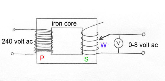 |
The diagram above shows a typical, highly simplified wiring diagram of a mains driven low voltage power supply as used in traditional brightfield microscopy. Note that the Voltage meter across the output is essential in a variable output unit like this, because many PSU's are supplied to power a range of bulbs with varying voltage ratings.
The Wiper picks up the low voltage output from the secondary coil at a point determined by the user, so varying its output voltage to the bulb's filament.
All this can be seen in a typical power supply below, though this particular example from Nikon uses an ingenious split secondary and double wiper to fulfil the same role as that simplified above.
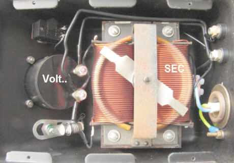 |
There is little to go wrong inside the housing principally because both its design and implementation are very good. Other manufacturers produce similar units with subtle variations such as a rolling wiper in Wild's low power AC supply unit :-
 |
Here the Wiper has a rolling carbonised wheel which contacts the windings as seen above. Again like Nikon's power supply unit it is very well made remaining perfecty useable to date. Leitz made a similar PSU at around the same time.
The Potential Problems
Whilst the longevity of these examples of low voltage power supply units is in no doubt, things can still go awry : most importantly the stability of the voltage output. So even though the transformer and its primary and secondary coils are highly unlikely to change their properties over time, the wiper's contact and mechanical end stops can wear or loosen. This potential long term flaw is common to all variable AC voltage PSU's, which varies in extent from one maker's example to another. Nothing should be taken for granted concerning this important aspect of voltage control, for if the maximum voltage stop creeps imperceptibly over a long period of time, the user will not be aware simply because the slight increase in light intensity is more than likely to go unnoticed........particularly if the voltmeter is either defective or defunct.
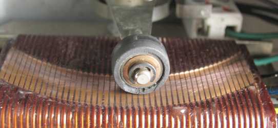
The image below shows a user adjustable wiper stop control knob on the exterior of the power supply. It's a little frail I think, and hints at being an afterthought in the design of this particular power supply. Note the screw which nips the knob to the wiper shaft, which is used here to limit the movement of the wiper inside the PSU. It's shown against the lower limit stop and when turned clockwise to increase the voltage to the bulb, comes against the upper stop which should of course be at the safe working voltage of the bulb in use.
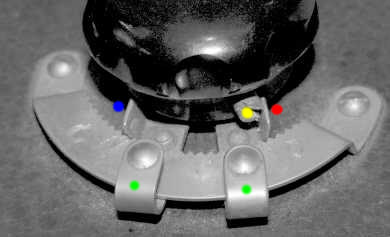 |
There are 2 potential problems with this form of wiper control. First the 2 upturned metal stops are liable to be bent further over from repeated use, and secondly the stop adjustments can themselves slip from their serrated seating positions in time. Though it works well enough by limiting the range of voltage output suited to the bulb in use, it is not really rigid enough and therefore the serrations can in time wear and allow an increase in voltage and so over heating the filament with inevitable consequences. Some might think the best solution is to ignore the stops and rely solely upon the reading of the voltmeter, and I can see their point, but owing to human nature in the main there is more likelihood of excess adjustment from occasional over zealous usage, more especially in conjunction with an unreliable or inaccurate voltmeter which is often encountered.
Other types of wiper stop are more robust and reliable, with virtually no change even after many years of use.......which is just as well since some are very difficult to access in order to adjust !
Safe Mode
Whether you have just obtained an old power supply unit like one of those above, or in fact wonder about your present unit's actual output voltage accuracy etc., it pays in the long term to check this even though all seems well. By doing so you will know if the mechanical wiper stop which fine tunes the actual maximum voltage to the lamphouse is doing its job properly.
A Simple Test
You'll need of course an accurate external independent multi-voltmeter, either of analogue or digital form. Their high input sensitivity, which is necessary for delicate electronic circuit board measurements is of no importance when used on our AC low voltage power supply unit, as its output impedance is very low and therefore virtually any accurate AC voltmeter will suffice.
The simplest way to check the output voltage is to connect the 2 leads of the AC meter to the sockets of the PSU that serve the microscope's lamphouse WHILST THE BULB IS AT ITS NORMAL OUTPUT level as indicated on the PSU voltmeter. Taking a voltage reading when the bulb is removed will only show a higher reading because the designed load is absent. Just pull out the banana plugs in the PSU a little to facilitate application of each of the 2 test meter leads to them. The reading on your meter will then be effectively the same as that across the filament inside the bulb. So comparing your testmeter's reading with the PSU's voltmeter couldn't be simpler.
The Result
Most likely the readings off your meter will compare within 5-10 % of those off the PSU's voltmeter. But all we are really concerned about is excessive voltage across the bulb, and though a difference of around 0.2v-0.4v in light outputting terms is hardly significant, the bulb's working life will be shortened, albeit to a limited degree. In any case a note of the difference between both meters can be made and any discrepancy between the PSU's voltmeter and the test meter can be marked onto the PSU's meter and used as a reference thereafter. If you can alter the wiper stop to limit the maximum voltage after checking with an external voltmeter then so much the better.
I try to keep the voltage down a little erring on the under powered side of the rated range and alter the wiper stop if it is easily accessible.......or if not then marking on the PSU's body clearly where the voltage limitations occur.
Heat Dissipation Efficiency
The most undesirable aspect of high wattage bulbs is of course their heat generation, which can be considerable, and is broadly speaking proportional to the power rating of a given bulb. A rough guide using the simple formula : Voltage x Current yields the approximate power generated by the bulb's filament and is expressed in Watts. So a bulb with a rating inscribed on its collar........ : ( 6.0V 4A ) .......would output around 24 watts ( ie 6x4 ) of light and heat energy. The heat is considerable given that most inbuilt lamphouse units are compact affairs often buried for obvious reasons in the microscope's base where ventilation is limited. In most cases the desirable heat loss is accomplished either by convection currents of air and/or by conduction through metallic casings. If there were no heat loss from the bulb, then the filament's temperature would rise, rapidly reaching its melting point then 'pop' .
Clearly then, heat dissipation is of prime importance in the lamphouse, and not only to keep the bulb working, but to sustain the longevity of the bulb's working life too. There are so many mechanical variations of lamphousings that specific attention for each would be impossible to cover in this basic article. Suffice to say however, that the majority of well established stands have lamphousings that are adequately ventilated, though there is clearly some variation of opinion between the manufacturers as to how this should be achieved.
If like me you have had a difficult time finding a suitable replacement bulb then by all means experiment with alternatives, but be mindful of the potential differences in heat output if you choose to replace say a 15 watt standard bulb with one which is one of higher wattage and obviously outputs more heat. Application of common sense can usually resolve the heat dissipation problem, by increasing the area of the ventilation ports that already exist, but replacing say a 15 watt bulb with a 50 watt bulb would almost certainly end in problems of one kind or another.
Final words
If therefore your bulb's legend indicates a voltage rating of say 6.0- 8.0 volts then the wisest interpretation of this would be to limit your PSU's ouput voltage to no more than 6-6.5 volts. For the average observing session this slightly lower rating will be more than adequate for the average eye and digital camera, and will guarantee a much longer filament life. In fact I only load a 50 watt 12 volt tungsten halogen bulb to 10 volts simply because its output is white enough and bright enough for all my work.
But the most important point to make in operational use of the PSU is to 'wind' up the voltage from scratch slowly over say a few seconds to reduce the rapid expansion around that delicate weld on each side of the tunsten filament. The durability of the modern tungsten halogen bulbs is in part directly attributable to the absence of welds within the capsule.
| All comments welcome by the author Paul James |
Microscopy UK Front Page
Micscape
Magazine
Article
Library
Published in the March 2010 edition of Micscape.
Please report any Web problems or offer general comments to the Micscape Editor.
Micscape is the on-line monthly
magazine of the Microscopy UK web
site at
Microscopy-UK