|
|
|
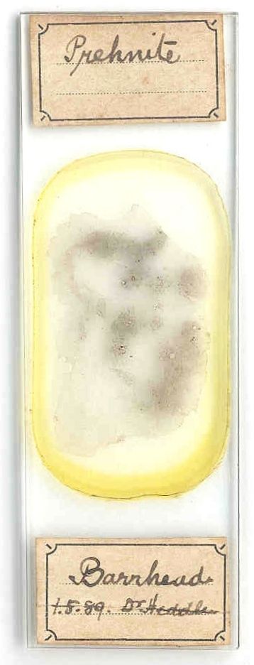
In the latter half of the nineteenth century, Dr. Matthew Heddle broke with the help of heavy hammers many different minerals out of the rocks near Barrhead, Scotland. He then skillfully created large, thin sections of minerals for microscopic analysis. It is my pleasure to present one of Dr. Heddle's excellent mounts of thin sections of prehnite, which is dated 1889. (For an image of this slide see Fig. 1.) I studied this slide under a compound microscope with two polarizers and used diascopic illumination. |
|
Dr. Heddle, mineralogist and chemist, is one of the most famous mineralogists and geologists of Scotland. He wrote a classic textbook about 'The Mineralogy of Scotland'. Fortunately, there is an excellently written biography of M. F. Heddle available from the Edinburgh Geological Society (located at http://www.edinburghgeolsoc.org/z_39_02.html). - Dr. Heddle recognized the importance of thin-section microscopy, a technique that allows geologists and mineralogists to study the crystal composition of various rocks. |
|
Prehnite (class silicates), which is semitransparent to translucent, is a secondary or hydrothermal mineral that occurs in veins and cavities in mafic volcanic rocks. (BTW, a rock dominated by dark colored minerals such as pyroxene and hornblende is called a mafic rock.) Prehnite is a typical product of low-grade metamorphism. Regarding the crystal symmetry, prehnite has an orthorhombic crystal structure with an mm2 point group. One is able to cleavage prehnite easily along the {001} crystallographic axis but only poorly along the {110} axis. Its hardness is around 6. The chemical composition is Ca2Al2Si3O10(OH)2 (calcium aluminum silicate hydroxide). Prehnite was named after its discoverer, Colonel Hendrik von Prehn (1733 - 1785). - Much more information about the mineral prehnite is available from the Amethyst Galleries. |
The preparation of a thin section of rock is a highly technical process, which requires
time and skills. The procedure involves several steps:
To check uniformity of thickness, one checks the maximum interference colors of known minerals under crossed polarizers (e.g. a faint straw yellow is the maximum interference color among grains of quartz). Two polarizers are said to be crossed when one polarizer polarizes the light in such a way that it is completely blocked by the second one. |
|
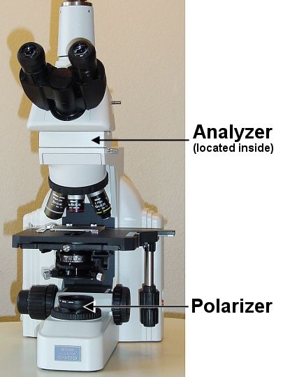
I added two Polaroid sheets, or polars, to a Nikon Eclipse microscope (see image on the right side). A polar is a polarization device that can be used to easily demonstrate linearly polarized light. One polar (the polarizer) was put below the condenser and a second polar (the analyzer) was placed between the objective and eyepiece (just below the tube lens of the trinocular viewing body). I purchased the Polaroid sheets from Edmund Industrial Optics for around twenty US dollars. This is most certainly not a professional polarizing microscope, but it works quite well for simple polarization microscopy. |
|
|
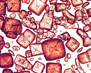
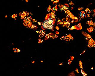
When looking at petrological slides with crossed polars, many different color variations might be noticed. The beautiful colors are caused due to double refraction in birefringent crystals. In a nutshell, in a birefringent crystal a ray of light, which penetrates into the crystal, is split into two rays that follow separate paths. One ray is called ordinary ray or O ray and the other one is called extraordinary ray or E ray, each of these rays is linearly polarized. For more information about polarization microscopy, I refer the reader to [1], [2] and [3]. For the reader new to polarization microscopy, I suggest a very simple experiment. After installing the two necessary polars into the optical path of a compound microscope, this system is ready to explore the difference of sugar and salt in polarized light. It is very easy to find the sugar crystals (see images below). |
|
|
Both images show the same sugar and salt crystals at low magnification (objective 4x). On the left side, the polars are aligned (not crossed), and on the right side, the polars are crossed. |
|
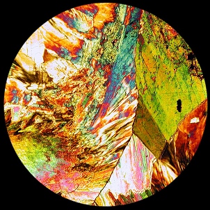
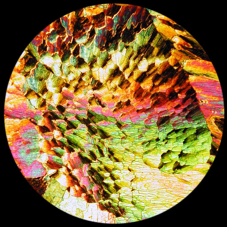
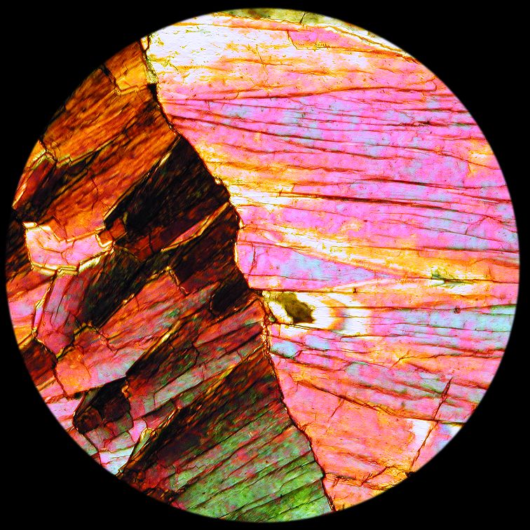
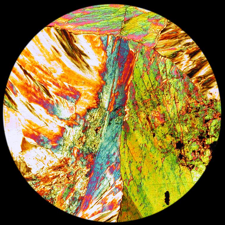
With a Nikon Coolpix digital camera (model 990), which is connected with the above microscope, I took the images of prehnite illustrated in Fig. 2, 3 and 4. I made sure that the analyzer and the polarizer were crossed, which turns the background into a very dark green. (BTW, theoretically, the background should appear black. But strain (due to stress) in the lens system of non strain-free lenses, causes the light to change its polarization while passing through the glass.) A professional polarizing microscope equipped with retardation plates (compensators) can be used to investigate the crystal structure of such a thin rock section. From the amount the polarization is changed by various crystals located inside a thin section, the mineralogist and the geologist can deduce the chemical composition. Polarization microscopy is an important analytical tool. |
|
I want to thank Dr. Fei Liu for many suggestions and stimulating discussions. The technical support of C&N for designing the HTML version of this article is greatly acknowledged. Last but not least, I thank all anonymous supporters who provided assistance and equipment. |
|
Comments to the author, Gregor Overney, are welcomed.
Please report any Web problems or
offer general comments to the
Micscape Editor,
via the contact on current Micscape Index.
Micscape is the on-line monthly magazine
of the Microscopy UK web
site at Microscopy-UK.