|
Köhler Illumination – not again!!! by Fritz Schulze, Canada |
Pages and pages on Köhler illumination have been written in a number of books, going into much theoretical detail and often rather confusing. One book I have doesn’t even mention Köhler at all and it was published in 1946!
So I decided to add my own 5 cents worth in an endeavour to simplify things a bit.
I like similes. They can often explain things clearly for everybody to understand. So here is my Köhler simile: the sewing machine! Don’t laugh – read on.
My wife is a quilter. Her sewing machine, embroidery machine, and serger are the equivalent of my lathe, drill press, and table saw. Before she can begin to sew, she has to ascertain that the thread in her sewing machine is carefully threaded through all the loops, hooks, and eyelets of the machine. Furthermore, the tension of both the upper and lower thread have to be exact in order to obtain a proper seam (One chap once neglected this rule on his loom and so, inadvertently, invented the bath towel! So I am told).
The light in the microscope corresponds to the thread in the sewing machine. It, too, has to be threaded carefully and correctly through all the lenses and diaphragms in order to achieve a satisfactory image of the object. Now the purpose of Köhler illumination can be described in one sentence:
To provide an even, homogeneous illuminated field and allow the microscopist to adjust the illuminated field without affecting the brightness and to adjust the brightness without affecting the illuminated field.
The first
microscopists used daylight via a mirror, later on oil lamps came
into use. Their light was somehow directed into the specimen and that
was it. As demands increased, collector lenses or water-filled glass
globes were interposed to concentrate the light. It was when the
first electric light sources came into vogue and the uneveness of the
filament started to show through that something had to be done.
So-called critical illumination which projected the light source into
the specimen was fine with oil-lamps having a large fairly
homogeneous flame but disastrous with filament lamps.
The light
path in a microscope consists of a series of lenses, apertures and
focal points. Each of them has a predertemined and interrelated fixed
position and purpose. The lenses we all know: basically the
condenser, the objective, and the eyepiece. Add to these the
collector and the eye and you have the total optical system. Without
going into too many details, let’s accept the optical system as
it is and explain how it works (Sorry, but we can’t do without
some theory!):
A picture tells us more than a thousand words. Therefore, let’s look at the schematic (Fig. 2) of the image-forming ray path: The arrow symbol represents all the planes conjugated to the specimen (plane), namely, the field diaphragm which is projected into the specimen plane by the condenser, together with the specimen it is in turn projected by the objective into the image plane of the eyepiece and via eyepiece and the observer’s eyelens onto the retina (or film, in case of a camera). I shall call these the image planes.
Superimposed to this image forming ray path is the illuminating ray path. The filament symbol represents all the conjugated planes relating to the light source (I shall call these the filament planes): the collector projects the filament into the condenser focal plane (aperture). The condenser projects it into the objective’s rear focal plane (exit pupil) , the eyepiece again projects it into its “eyepoint” i.e.exit pupil, where the observer’s iris is also located. You can’t see the filament because it is not projected onto your retina.
You will notice that image and filament planes alternate throughout the system. To sum up: as each filament or image plane has a precisely determined and interdependent position, axially and laterally, any tampering with these can have considerable impact on the image. Understanding their purpose can help you to get the most out of your instrument.
What are the practical implications of the Köhler system?
First, we learned that each plane, be it image or filament, has a fixed location. So you don’t rack the condenser down if the image is too bright (you either close the condenser aperture diaphragm, use an attenuating filter, or reduce the lamp’s intensity). You keep the condenser centred, don’t close diaphragms indiscriminately, and keep the filament bulb carefully centred.
Second, If you wish to illuminate a larger field for a low power objective, swing out the condenser front lens (if it has one) or use a large field condenser. Do not rack the condenser down. Open the field stop only enough to illuminate your field of view. Ground glasses are used as a last resort.
Third, any dust or dirt in or immediately near an image plane will be visible with the specimen. Therefore, these planes in particular have to be kept very clean: the cover glass over the field diaphragm, the coverslip, the underside of the slide and even the front lens of the condenser, and any graticule disc in the eyepiece. To find out where the dirt is, start rotating the eyepiece. If the dirt rotates with it, clean it, particularly the outer topmost lens. If not, move the specimen. If the dirt does still not move, clean the cover glass of the field diaphragm (if it has one). Lastly you can rack the condenser down or decenter it to see if the annoying dirt sticks to it. Conversely, you can – particularly if you have an achromatic condenser – put a pointer on the field diaphragm which will show on the specimen (a neat trick to impress friends with! Close the condenser aperture a bit, though. Equally, any scale or pointer you place in an image plane will be seen).
Fourth, if you use a standard eyepiece while wearing eyeglasses, your eye’s iris can’t any longer be in the same plane as the eypiece’s eyepoint (exit pupil) and your field of view is severly restricted. You need a modern so-called high eyepoint eyepiece specially designed for spectacle wearers. If you don’t suffer from astigmatism, you can set in a modern instrument your refraction (diopters) on the corresponding tube sleeve, e.g. –3D, and work without glasses.
Fifth, start using the microscopist’s magic weapon: the phase-contrast auxiliary microscope (or the Ph position in the Optovar if you are lucky to have a Zeiss microscope so equipped). It is like the doctor’s stethoscope, a most useful diagnostic tool. You insert it into the tube instead of the regular eyepiece and focus it on the objective’s rear focal plane (exit pupil). You will see the lamp filament (Is it centred? Does it fill the entire exit pupil?). You can close the condenser aperture diapragm (Is it centred? When open, does the light fill the exit pupil?) You can see any air bubbles in an oil immersion. You can see any dirt that fell into the objective. And you can, of course, see if the phase rings are properly superimposed when working with phase contrast. Anything untoward, off centre or vignetting you notice has to be identified and corrected.
Most modern microscopes are already set up for Köhler illumination. But what I you have a simple student microscope or an antique instrument equipped with a mirror only? To arrange for Köhler illumination in these cases will require some patient manipulation.
I set up an old Leitz microscope with an #5 (~ 30x) objective, a 1.2 n.A. condenser, and a # 3 (~8x) eyepiece*, together with an old CTS microscope lamp with iris ( having a centrable and focusable bulb 6V 30W with flat square filament) (Fig.3). I directed the light onto the microscope mirror and adjusted the mirror to illuminate a specimen and focused it. Holding a paper under the condenser I found that I had to move the lamp further away in order to obtain a large enough image of the filament. At a combined distance of 30cm from lamp via mirror to condenser, the image of the filament was approx. 12x12mm after I focused it. The diameter of the condenser aperture was 30mm! (Fig.4)
Next I closed the iris of the lamp and observed it on the specimen (Fig.5). I focused it by adjusting the condenser (it helps to close the condenser stop somewhat to increase the contrast or the field stop may be “hardly” visible), centred it by means of the mirror, and then opened it to fully illuminate the field of view. One must never illuminate more than what covers the field of view in order to reduce stray light from the surrounding area.
Then I placed the auxiliary microscope and observed the objective’s exit pupil (Fig.6). The filament covered about 80% of the circular exit pupil and was slightly off centre. I centred it with the centring screws of the lamp. So it was not large enough, the lamp would have to be removed even further, but I left it at that. For any objective with a higher aperture I would have to rearrange the lamp to achieve a much larger image of the filament. The condenser diaphragm, when closed, could be clearly seen. I opened it just enough to cover the filament (Fig.7 -a rule of thumb is to close it normally to about 80% anyway in order to obtain adequate contrast without unduly affecting the resolution), then checked the image with the regular eyepiece: it was perfect (Fig. 8). I had my Köhler illumination, albeit with considerable manipulations.
On the old microscopes the condenser usually can’t be centred relative to the objective. On a modern microscope with built-in illuminator, the fixed field stop acts as benchmark for centering the condenser. This is about the only adjustment you may have to make, the rest is only to adjust the field and condenser diaphragms for proper field and contrast.
A microscope is a wonderful and magnificent instrument and as such it requires understanding and careful handling. Only then can it give the microscopist full satisfaction. It is like a car: the more you understand how it works, the better can you drive it. Of course, some people just get in, turn the key and roar off in a cloud of burnt rubber.
* The photomicrographs were taken with a Leitz Periplan 10x/18 M high eyepoint eyepiece which screws directly onto my Nikon Coolpix 995 digital camera
Fritz Schulze
Vineland, ON, Canada
All comments to the author Fritz Schulze are welcomed.
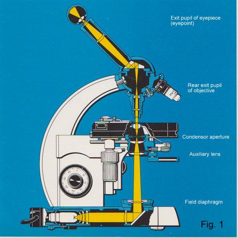
Fig.1 Cross section of a modern microscope (Zeiss Standard 18) showing illuminating ray path
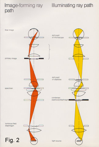
Fig. 2
Schematics showing the image forming and illuminating ray paths.
Figs. 1 and 2 from
Brochure K 41-006-e “Worthwhile informations about the
function of your
Zeiss microscope” by Carl Zeiss Oberkochen 1984.
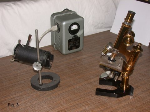
Fig. 3
My experimental set-up with the Leitz microscope and CTS
(Cooke,Troughton & Simms Ltd.) microscope lamp.
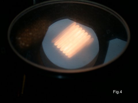
Fig. 4 The filament projected on a piece of paper under the condenser (seen through the mirror).
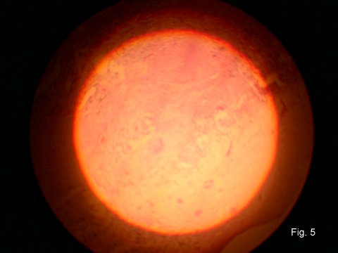
Fig. 5 The field diaphragm focused and centred. You can see at its upper edge the secondary image caused by the reflection on the glass surface of the mirror. (The specimen is not optimally focused.)
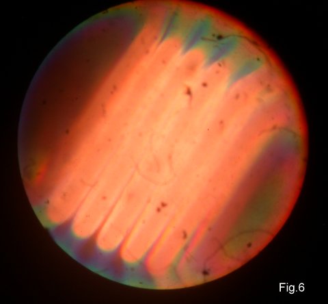
Fig. 6 The filament imaged into the objective’s exit pupil, seen through the auxiliary microscope, after it has been centred.
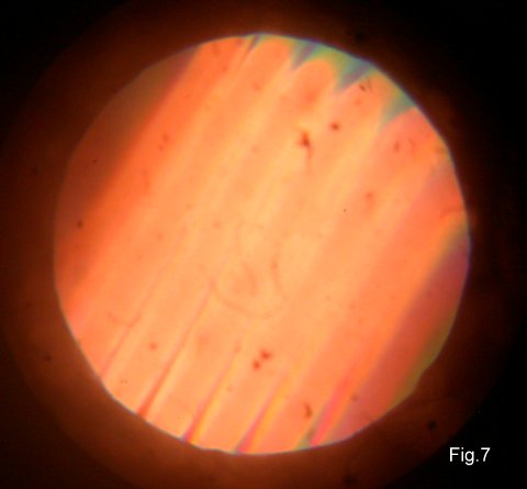
Fig. 7 The condenser diaphragm closed to encompass the filament (the apparent larger size is due to my cropping of the picture and the computer program subsequently resizing the image).
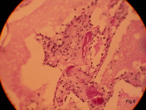
Fig. 8 A final view of the specimen (a lung section for TB check).
Also: Prof.August Köhler (1866 – 1948)
Microscopy UK Front
Page
Micscape
Magazine
Article
Library
Published in the May 2012 edition of Micscape Magazine.
Please report any Web problems or offer general comments to the Micscape Editor .
Micscape is the on-line monthly magazine of the Microscopy UK website at Microscopy-UK .
© Onview.net Ltd, Microscopy-UK, and all contributors 1995 onwards. All rights reserved. Main site is at www.microscopy-uk.org.uk .