and Step-by-Step Sample Preparation
Ulf Griesmann, Gaithersburg, Maryland, USA
Bone is an educational
and rewarding subject for the amateur microscopist. In this
article I describe the preparation of bone samples for optical
transmission microscopy and illustrate the remarkable
observations that can be made with rather modest means. The
preparation methods described here may also be of interest to
students and their teachers who want to take a closer look at
one of the most astonishing, and astonishingly complex,
natural materials. The first part of this article describes
the preparation and mounting of bone thin sections. In
the second part, several micrographs are discussed that
were made using a simple LOMO Multiscope microscope (known as
Biolam outside the US).
Bone is opaque and must be prepared in the form of thin
sections for the brightfield transmission microscopes that are
most readily available to amateur microscopists or in
educational settings. One advantage for the amateur is that
the preparation of bone specimens does not require the use of
dangerous chemicals for fixing and staining, because most
features can be observed without elaborate specimen
preparation. Without a saw microtome, making thin sections is
tedious work, but the procedure described in the following
paragraphs yields sections that allow for surprisingly good
images. Fig. 1 shows a piece of bovine (cow) long
bone, about one inch in length, that was cut from a fresh leg
bone with a saw. The bone section was cleaned with warm water.
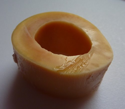
Figure 1: About one
inch (25 mm) long section of bovine long bone.
A complete imaging of the complex
three-dimensional structure of bone requires multiple
transverse, longitudinal, and radial sections. Here I will
concentrate on the preparation of a transverse bone
section. The finished bone section will be bonded to a
microscope slide and so the first step is to grind flat
and polish the part of the bone that will be glued to the
slide. This grinding step is illustrated in Fig. 2. The
grinding is done using emerald paper from a DIY market
where paper with grit sizes down to 600 is commonly
available. Further polishing was done using a set of Micro-Mesh polishing
pads (shown in Fig. 3) for wood polishing with up to 12000
grit, which achieve a mirror-like finish. The samples can
be prepared either wet or dry, but it is much easier to
bond a wet sample to the microscope slide because suitable
water compatible glues, e.g. surgical glues, tend to be
very expensive. The bottom side of the bone does not have
to be finished all the way to a mirror finish because it
will not be viewed with the microscope, but it should be
fine ground without large, visible scratches.
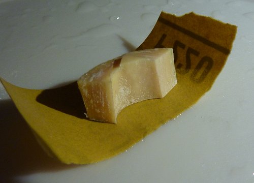
Figure 2: Grinding
the "bottom" of the bone sample.
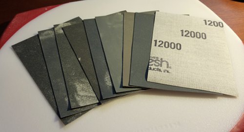
Figure 3:
Micro-Mesh polishing pads used for bone polishing.
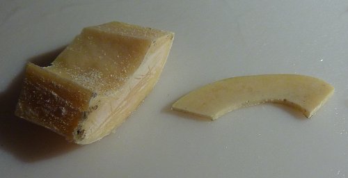
Figure 4: Bone slice with one fine-ground side.
Once the bone piece has been ground to
a fine finish, the piece is clamped in a vise and,
using a small hacksaw, a slice as narrow as possible
is cut from the bone as is shown in Fig. 4. Next,
the bone slice, like the one in Fig. 4, is cut up
into about 5 mm x 5 mm chips which are bonded to
microscope slides using a clear epoxy glue. Fig. 5
shows two chips, one a transverse section, the other
a longitudinal section, being clamped to microscope
slides while the epoxy glue cures. The clamping is
important to make sure the glue layer between slide
and bone chip becomes as thin as possible. Fig. 6
shows the result - a bone chip that is about 1 mm
thick bonded to a microscope slide. Wet samples can
be glued with acrylic superglue, which is somewhat
water compatible because the curing reaction is
catalyzed by water, but the result is a bond that is
much more fragile than the epoxy bond and much less
likely to survive the subsequent grinding and
polishing. Most of the ones I tried peeled off
during grinding. Bone chips that are kept for later
glueing can be stored in isopropanol if they are
destined to become dry samples or de-ionized water
in case they will remain wet. Purists can use
physiological saline solution or Ringer's
solution to temporarily store wet samples.
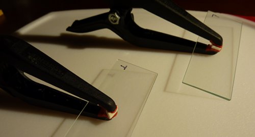
Figure 5:
Bone chips being glued to microscope slides.
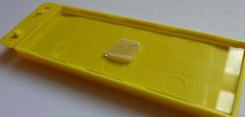
Figure 6: A 5
mm x 5 mm x 1 mm bone chip bonded to a microscope
slide.
The bone sample
must now be ground and polished to a thickness
between 25 µm and 30 µm. If the bone
section becomes too thin there will be nothing
left to look at; if it is too thick, the
structures near the surface will be confounded
by features that are buried inside the section.
The thin grinding is the most difficult part of
the sample preparation and it will require some
practice. Holding the slide between thumb and
middle finger and supporting the back with the
index finger, the thickness of the sample can
quickly be reduced by grinding with emerald
paper as is shown in Fig. 7. People with
allergies or concerns about, heaven forbid, mad
cow disease may want to wear a face mask when
preparing dry sections to avoid inhaling bone
dust. At this stage it is easy to get bored and
grind too fast; it is better to go slow than to
start over. The thickness of the section must be
monitored with a micrometer as is shown in Fig.
8. Once the thickness drops below about 200
µm a finer grit must be used for a while
and then the next finer grit and so on. The
purpose of the polishing is to remove the
scratches and the damage that is introduced in
the sample by the larger grit abrasives. As the
section thins, the grit size should be reduced
until a 25 µm thick section is obtained
that is polishded to a mirror finish with the
finest available grit. A successfully polished
section looks like the one shown in Fig. 9.
Finally, the polished section is wiped clean
with isopropanol or water and the section is
mounted under a coverglass. Dry sections can be
mounted with Mount-Quick (Daido Sangyo Co. Japan) or a similar medium, wet
sections may be mounted in glycerin gelatin.
(For wet mounted sections, the edges of the
coverglass must be sealed with varnish.) Fig. 10
shows a finished slide. A 25 µm thick
section still appears noticeable opaque. Wet
sections mounted in glycerin gelatin will become
more transparent over time because glycerin is a
clearing agent for bone.
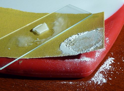
Figure 7:
Grinding of a thin bone section.
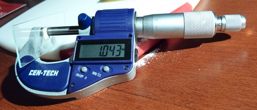
Figure 8:
Measuring the bone section thickness with a
micrometer.
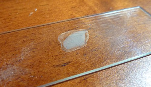
Figure 9:
A finished thin section.
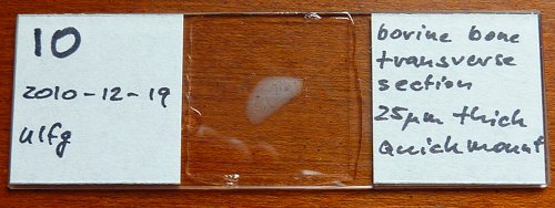
Figure
10: A finished slide with cover glass and
labels.
With
slides finished it is time to look at them
under the microscope! Figs. 11 - 15 are made
with my modest LOMO Multiscope microscope
that is fitted with a Motic 3 megapixel
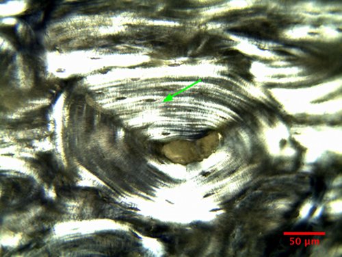
camera. Fig. 11 is a beautiful picture of
the fundamental structural feature of
compact bone - an osteon. Osteons are bone
columns made from concentric layers, or
lamellas (lamellae). The green arrow
in Fig. 11 points to one of the lamellas. At
the center of each osteon is a conduit,
called a Haversian canal, that carries
vessels for the blood and lymph supply. The
outer boundary of an osteon is the cement
line (actually a sheet) pointed to by a
yellow arrow in Fig. 11. The Haversian
canals at the centers of osteons are
connected in a ladder rung-like fashion by
canals that are called Volkmann's canals.
In Fig. 11, a Volkmann canal can be seen
branching off to the right from the central
Haversian canal.
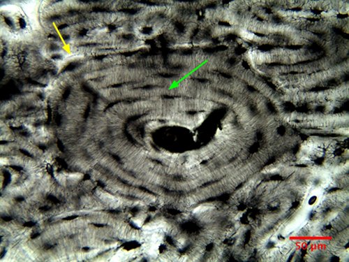
Figure
11: Osteon in a transverse section of bovine
long bone (20x, NA=0.65).
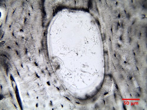
Everywhere along boundaries
between lamellae in Fig. 11 are small voids
that are more clearly seen at larger
magnification in Fig. 12. The voids are called
lacunas, or lacunae in high falutin (related
to the words "lake" and "lagoon"). They are
about 10 µm long and 4 µm wide.
Some of the lacunae can be seen as dark
shadows in Fig. 12 because they are buried
beneath the surface of the bone slice. Each of
the lacunae is home to a bone building cell
called osteoblast.
These cells have laid down a bone lamella
until they became imprisoned in the bone that
they have created. Their connection to the
outside is a vast network of small channels, or canaliculi, which can be seen in Fig. 12
connecting the lacunae within an osteon.
Canaliculi do not cross the cement line.
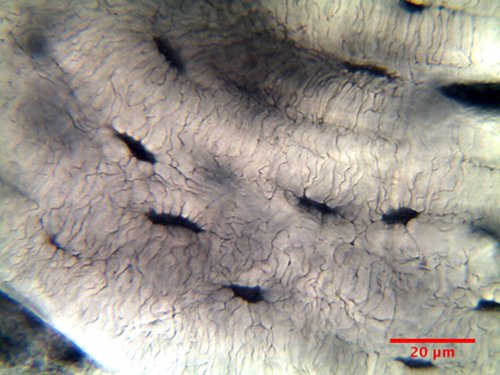
Figure
12: Lacuae and canaliculi in bovine osteon
(oil immersion, 60x, NA=1).
When the
light that enters the condenser is polarized
by placing a polarizer in the filter holder
and a second, crossed polarizer at the image
plane of the microscope objective, the
sub-structure of the bone lamellas becomes
visible. Fig. 13 is the osteon of Fig.11 but
imaged with polarized light. The green
arrows in Figs. 11 and 13 point to the same
location. The lamellas appear to have a
sub-structure made of layers that respond
differently to polarized light, which
implies that the structure and organization of the bone in these layers must be
different.
Figure
13: Bovine bone osteon in polarized
illumination (20x, NA=0.65).
A
particularly beautiful find is Fig. 14,
which shows an example of bone remodeling
and the creation of a new osteon. In a
living animal, bone is constantly modified
by carefully orchestrated processes of
disassembly and rebuilding. Bone is
dismantled by specialized cells, called osteoclasts, which
dig tunnels into the bone and release the
molecular building materials into the blood
stream. The bone tunnels are then populated
by osteoblasts
that build new osteons from the outside in.
The balance of these two processes
determines if the bone in a specific bone
area is strengthened or weakened. In Fig. 14
the beginning of a new osteon in the space
left behind by the activity of an osteoclast
is captured and the first lamellas that have
been laid down as part of the new osteon can
be discerned.
Figure
14: Bovine bone remodeling (20x, NA=0.65).
Finally, Fig. 15 is a lower
resolution image of a longitudinal section of
bonvine bone. The column structure of the
osteons in this part of long bone are clearly
visible - as are some amateurish bubbles in the mounting medium.
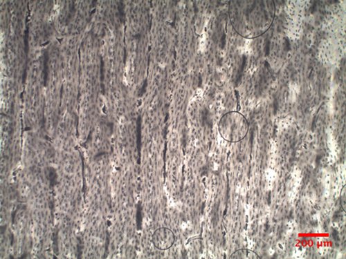
Figure
15: Bovine bone, longitudinal section (4x,
NA=0.12).
Figs. 11 to
15 are merely a glimpse of the complexity of
bone. A real slide is like a strange
country that awaits discovery and I hope
that some of the readers are inspired to
make their own bone thin sections and study
them with their microscopes. Higher
resolution versions of the bone images are
available for download. Readers
with an academic bent can go to their
library to learn more about bone and how it
functions. The famous book by Bruce Alberts
et al. "Molecular
Biology of the Cell", Garland Science, would be a good start.
All
comments to the author are welcomed.
Microscopy
UK Front Page
Micscape Magazine
Article Library
© Microscopy UK or their contributors.
Published in the
May 2012 edition of Micscape.
Please report any Web
problems or
offer general comments to the Micscape
Editor.
Micscape is the on-line monthly
magazine
of the Microscopy UK web
site at Microscopy-UK
© Onview.net Ltd, Microscopy-UK, and all contributors 1995 onwards. All rights reserved. Main site is at www.microscopy-uk.org.uk.