Different LEDs from different manufacturers operate at different maximum
continuous voltage, which in turn determines the maximum current flowing
through the LED. To protect LED and to provide stable light characteristics it
is necessary to limit the voltage output from the KIS-3R33S module according
to the specific requirements for each type of power LED, as specified by the
manufacturer.
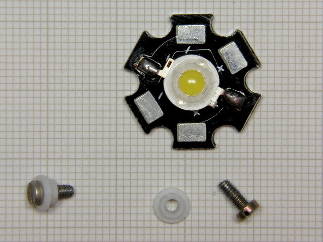
For power LED, which I have used, manufacturer has specified maximum
continuous forward voltage at
3.7 V for the 235 lm three-watt LED HPB8b-49K3WHB. Following manufacturer's
instructions, I have limited the maximum output voltage of the module so that
it will suit the LED. I also wanted to have the means of
continuous brightness adjustment so I used a potentiometer to vary the
brightness.
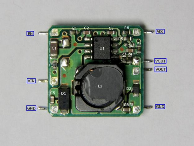
Necessary modification of the module consisted in removal and replacement of
three SMD resistors, done as follows.
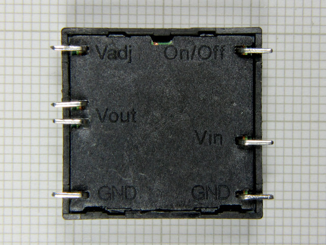
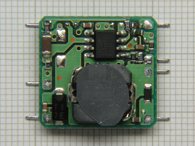
The module is very small, measuring 21x22x10 mm total. To modify it one must
remove the bottom cover and then remove module from its housing, not
difficult, the cover is snap-on type.
Resistors R3, R4 (both marked 513 i.e. 51 k Ohm) and R6 (marked 332 i.e. 3.3 k
Ohm) should be removed, and replaced. R3 and R4 with 39 k Ohm and 180 k Ohm
(order of placement is unimportant as they are connected in parallel).
Resistor R6 should be replaced with one of the 51 k Ohm resistors removed from
R3 or R4 positions.
The additional components are the logarithmic tracking potentiometer VR1 250 k
Ohm,
connected externally, with integral switch, which when the switch is engaged turns the DC-DC
converter ON. The two ceramic capacitors,
10uF /25V, one should be connected across VIN and GND and another across VOUT
and GND.
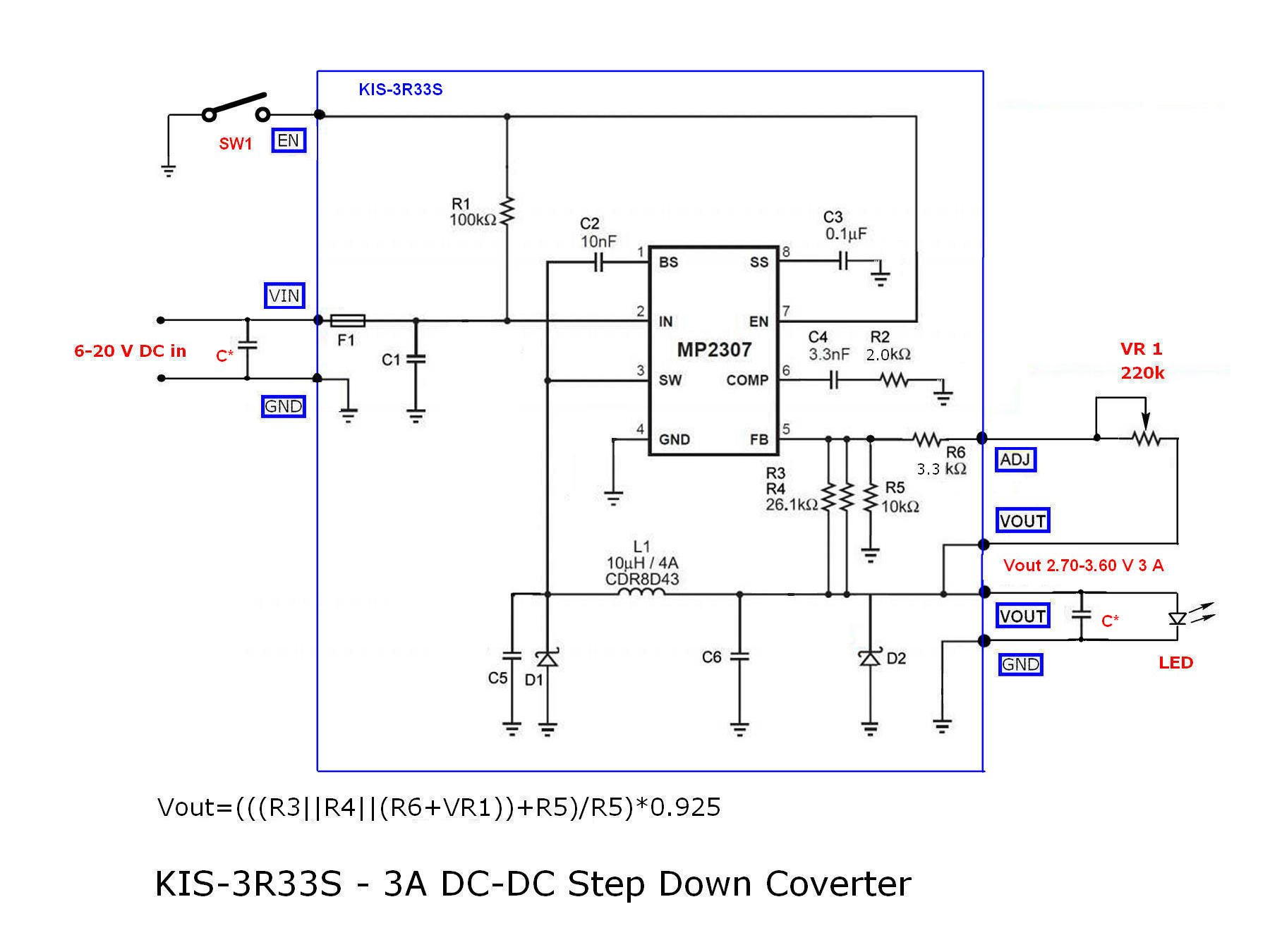
The value of the resistor R6 (51 kOhm), chosen to prevent voltage output falling below
2.70 Volts, as below that value LED will cut off. Combination of resistors R3,
R4, R5, R6 and VR1 determines the output voltage according to the following
formula:
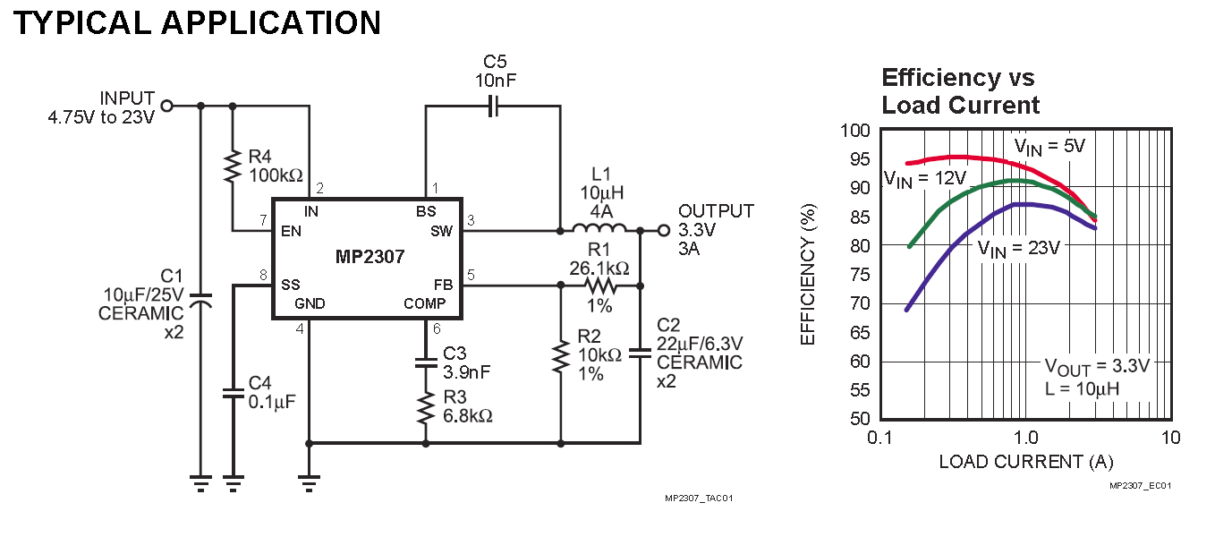
Vout = (((R3||R4||(R6+VR1))+R5)/R5)*0.925
Resistors R3, R4, R6+VR1 (R6 is connected in series with VR1) are connected in
parallel and are actually acting as one resistor. To calculate value of two or
more resistors in parallel:
Rx=1/(1/R1+1/R2+1/Rn)
in our case Rx=1/(1/R3+1/R4+1/(R6+VR1)) so Vout becomes:
Vout = ((Rx+R5)/R5)*0.925 (where R5 stays unchanged, as is, 10 k Ohm)
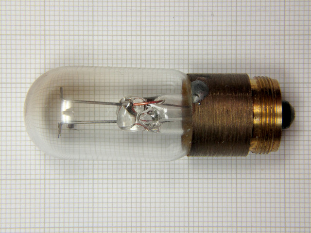
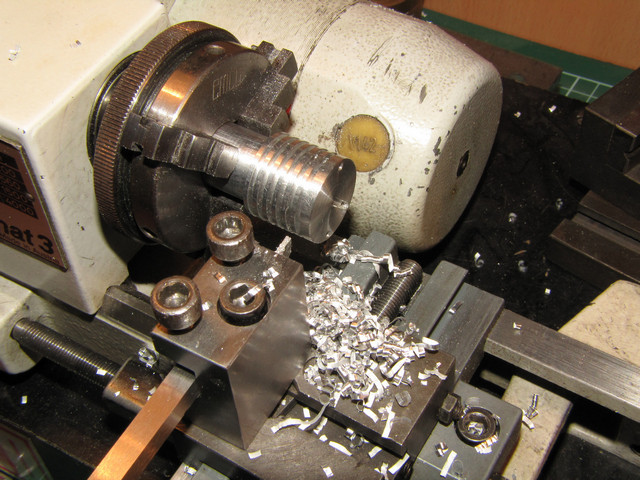
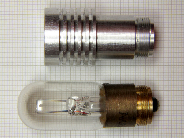
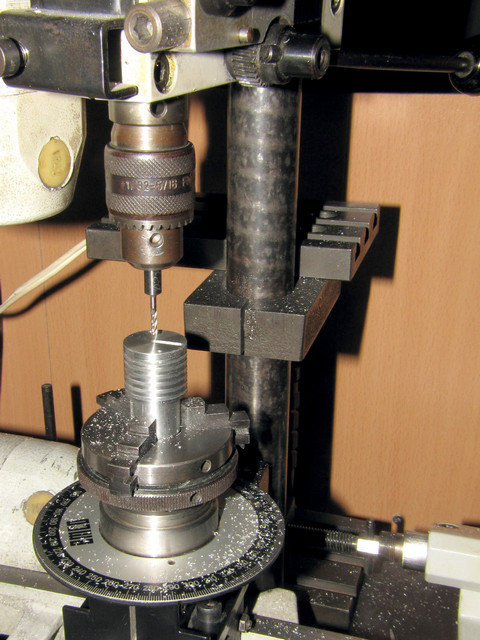
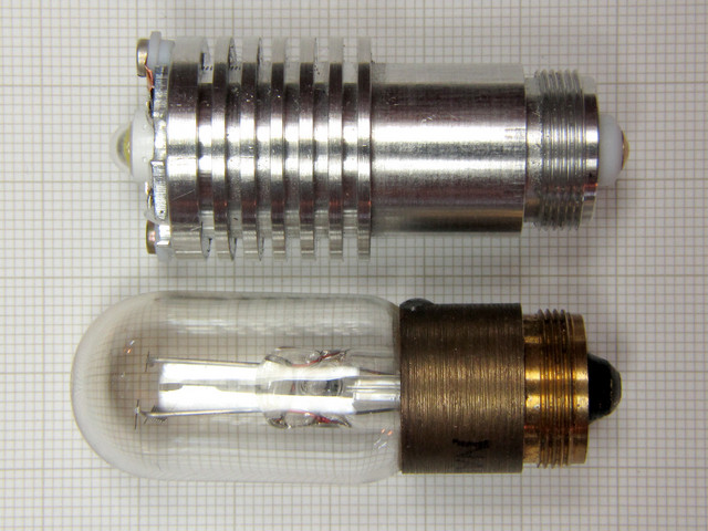
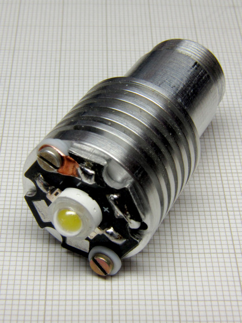
I have machined body out of
Duraluminium from a stock bar OD 7/8 (22.23 mm) that I already had which
was nicely fitting the need. The free end that originally was the glass
envelope of the lamp I have machined a number of fins increasing the surface
area to serve as a heat sink. I drilled the body through its length to accept
a wire supplying V+ to
the power LED. I let the body be at ground potential, thus eliminating need
for a second wire.
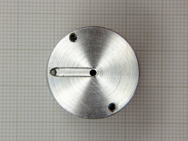
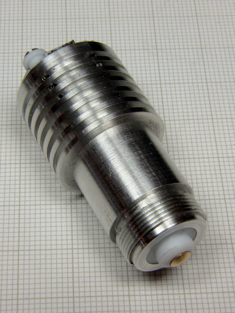
The
bottom part, I drilled larger hole and then pressed in a short length of Teflon
rod which I drilled partly through and press fitted a short brass rod to which
I soldered one end of a short length of Teflon insulated 22 SWG silver plated wire to
it.
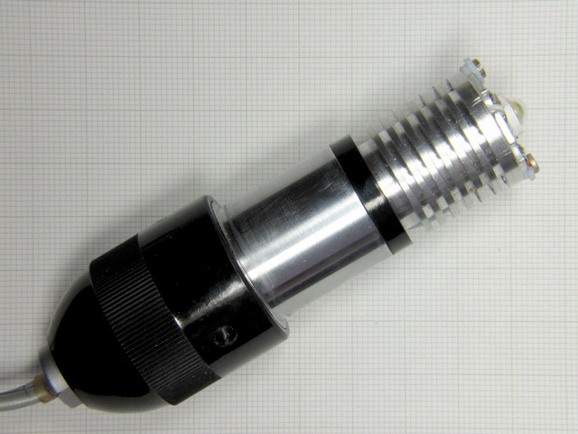
The
use of original power supply was retained with the addition of a full wave
rectifier and a filter capacitor placed in the same box with the DC-DC
converter, thus allowing for a quick return to use of incandescent lamp if the
need ever arises.
Note: If LED flicker is experienced, then the 'Soft Start' capacitor C3, part
of the module, should be removed.
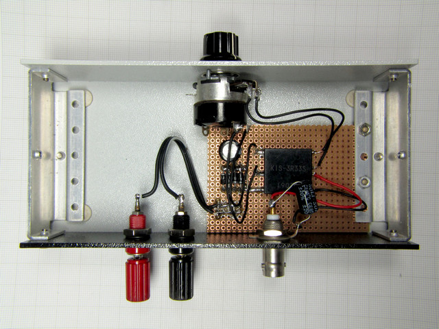
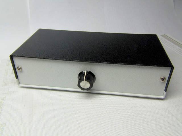
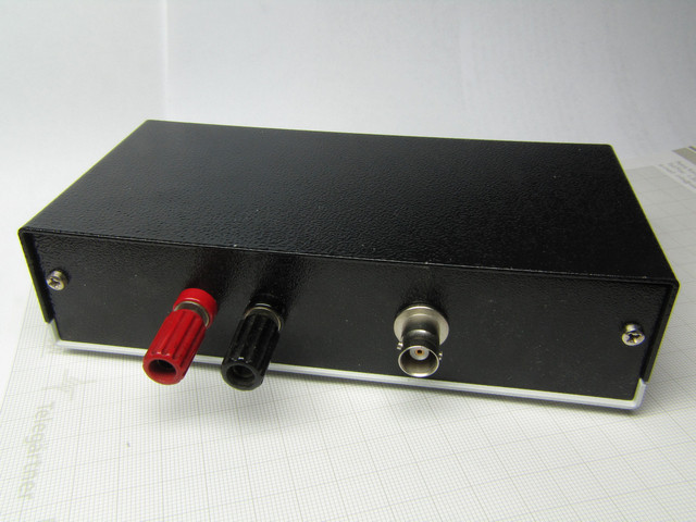
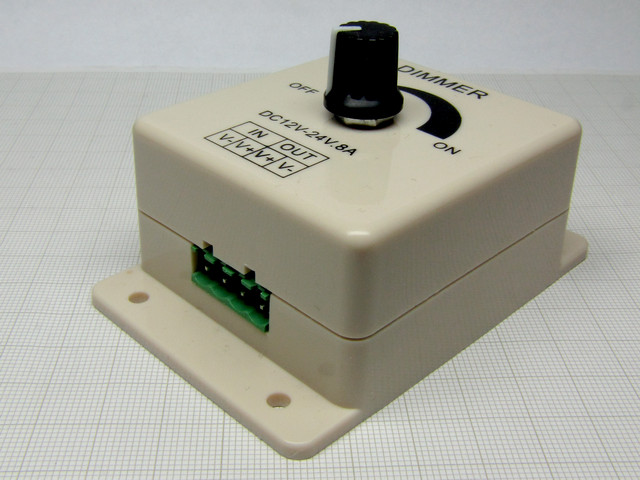
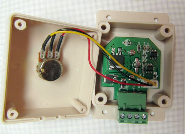
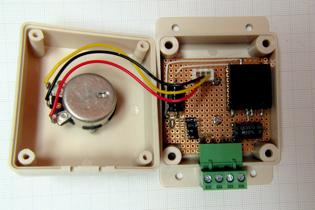
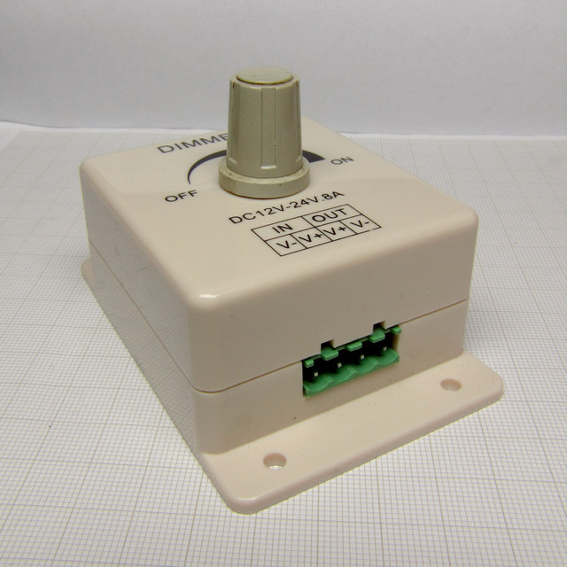
I found this box offered on eBay from a Chinese seller, at the cost of only US$5, free shipping. A power LED driver requiring DC input and giving DC output, a pulse width modulated unit based on NE555. Although not at all suitable for driving microscope LED illumination I bought it and used the housing only. It can be seen from the images below how the Chinese Dimmer looked like originally, inside. I have removed the original PC board that was in it, replaced potentiometer as well, as original was unsuitable with the resistance value of only 1 kOhm, thus I placed my protoboard with KIS module inside using the two existing mounting posts to fasten protoboard to the bottom half of the box.
The housing is rather smallish and perhaps more desirable that way, as the bench with the 'scope is almost always crowded with many things. Size of the housing is 60x65x35 mm (WxBxH), height with the pot knob is 57 mm, and the base is 60x90 mm with two 4 mm holes on each side should fixing it to the bench be desired.
| KIS-3R33S | module | 1 pc. | ||
| Power LED | 3W | 1 pc. | ||
| Resistor SMD 603 | 56k | 1 pc. | ||
| Resistor SMD 603 | 68k | 1 pc. | ||
| Potentiometer with switch | 250k log | 1 pc. | ||
| C* Capacitor X5R SMD 1206 | 10uF/25V | 2 pcs. | ||
| Proto board |
2. HPB8b-49K3xWHBx data sheet - HUEY JANN ELECTRONICS INDUSTRY CO., LTD.
3. MP2307_r1.9 data sheet - Monolithic Power Systems, Inc.