| Vertical Cell Observation Techniques | |||
2 DIY contraptions for the microscope for viewing Hydra et al in vertical cells By Paul James, UK
|
| Vertical Cell Observation Techniques | |||
2 DIY contraptions for the microscope for viewing Hydra et al in vertical cells By Paul James, UK
|
I'd never been too keen observing organisms such as Hydra in a vertical cell with conventional low power stereo microscopes, because of the awkward angles involved. This fascinating creature can be viewed in comfort using our existing compound microscopes, by adopting one of the following techniques. The gadgets I've made for this type of observation are quite simple, but do involve one optical item.....a right angled prism, or failing this a surface aluminised plane mirror. If you fancy observing this fascinating organism in comfort, then take a look at both methods, and if one of them appeals there is further information on construction etc further on below.
Method A
I've started with the more unconventional method first, and though it may appear to be unusual and does takes time to get used to, it has advantages of simplicity and requires a smaller prism than the second method.
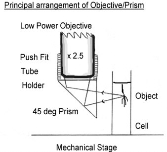
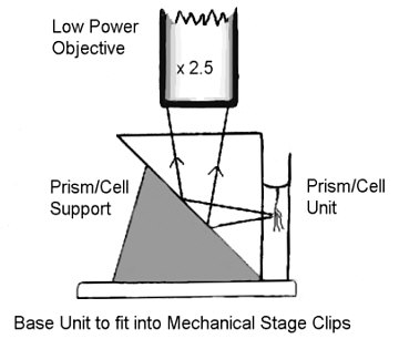
The diagram shows how the standard microscope can be temporarily modified to observe a vertical cell. Apart from the cell which is attached to a plate resting in the mechanical stage, the microscope is operated unconventionally :-
The cell, which is mounted on a plate held in the same way a slide can be moved into position and focused with the mechanical stage. The normal focusing mechanism is used to raise or lower the prism housing to scan the object vertically, and the other movement of the mechanical stage moves the object from side to side.
The prism must be orientated to align on one of the mechanical stage's axes for obvious reasons, and the binocular head may have to be turned to allow the image to appear upright too. If the binocular head is of the fixed type, the prism must face the observer or the back of the microscope depending on optical design of the binocular head. Though the image is erect we might see mirror imagery with some binoheads. As you can easily imagine the controls take a bit of getting used to, but practice makes perfect !
Method B
This alternative method is very similar to the first, but the prism is free of the objective, and also forms part of an integral cell, reducing the glass/air surfaces used and making for a simple and compact unit.
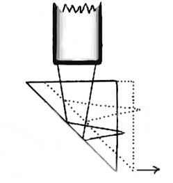
The difference here has more to do with the operation of the 'scope, and moving the stage from left to right causes the reflected rays to scan the subject in the vertical mode, and the 'fore and aft' motion of the stage scans the subject side to side.
Once the subject is focused, and assuming that the prism is supported accurately, the stage controls both vertical scanning as well as lateral. It might not be initially obvious, but the vertical scanning is caused by the 45 deg reflection angle keeping the length of the light path from subject to objective constant. So when the stage is moved right, the observer sees the upper part of the subject/cell and visa versa. :-
Naturally, tweaks of the fine focus will have to be made when scanning the subject, as we would do with the microscope when scanning slides in normal circumstances.
Objectives
Having considered the basic ideas for both methods we now have to turn to some practicalities.
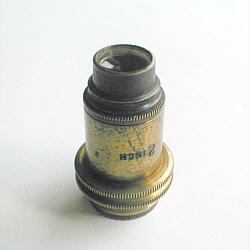
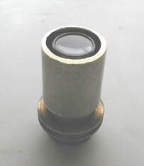
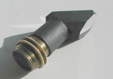
With the prism in place it can be seen that the working distance between the subject and the front element of the objective is quite large. To a great extent this depends upon the physical size of the prism, the larger these are the greater the working distance required. It is entirely likely when using a larger prism, that the low power objective ( x2.5, x3, etc..) will be unable to focus the object even if the objective and cell are right up against the prism faces. If we have no lower power objectives that will focus through the prism we must either try to achieve focus by using a smaller prism, or start searching for an older low power objective like the one illustrated below which is a four element design using two achromatic doublets and is of 2" focal length. At a guess this objective is equivalent to a x2-2.5 objective of the modern type.
These objectives can be used with only one of the doublets or pairs in place, so considerably increasing the working distance, and reducing the magnification by about half which is very useful at times. Some manufacturers have made very low power objectives such as a x1 ( Zeiss ).
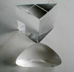
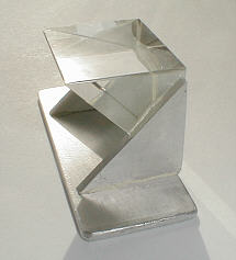
Prisms
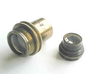
There are fundamentally two types of prisms which will serve our purpose, both sharing the same principles of reflecting light efficiently by way of total internal reflection through 90 degrees. The prism shown at bottom of photo is the type used in field binoculars and will be ideal for Method A as it is compact and usually quite small. The other is a plain right angled prism and is usually used in 'right angle' eyepiece attachments for telescopes, and is usually larger than the others and is ideal for Method B
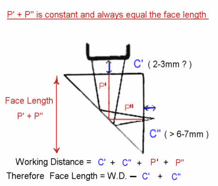
Determining the size of prism required
Measure the working distance of the objective you would like to use to the nearest mm. and determine the MAXIMUM face length of the prism, ignoring the diagonal length :-
If the working distance of your objective is say 30mm., then using the clearance values given above, the maximum size face length of the prism would be :-
30 - C'( 3mm ) + C''( 7mm ) = 20 mm face length
Remember this is the Maximum size of face length of prism, and a smaller one will be suitable.
Prism sources : Ex WD stockists or old redundant equipment, ie old tatty field binoculars etc..
Mirrors
Although a plane mirror will perform as well as a prism, the aluminium coating is easily damaged ( some are coated with tough silica coatings and are very durable ) and cannot be effectively cleaned by simply wiping with tissue without scratching and making the surface hazy and eventually becoming useless. I have therefore concentrated on using prisms, but realise that someone may be able to think of a way of utilising a plane mirror to their advantage. In the event of not being able to get a suitable prism, a surface aluminised mirror will certainly do the job well, but would require an 'undersling' type support for Method B which may cause some difficulties when trying to achieve the precise 45 degree angle.
Prism mounting .......... for Method A
Given the fact that is it most likely that only one suitable objective will be used, it matters little that we make a specifically designed attachment for this lens only. A straightforward method is to attach it to the objective using a slip collar which has enough friction to keep the device securely in place, yet be able to be turned or removed easily without damaging the exterior surface of the objective.
Before making any attempt to make a permanent fixture to hold the prism onto the chosen objective, it goes without saying that some experiments with prisms and sticky tape have to be made to satisfy ourselves that the combination is a practical proposition !
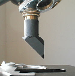
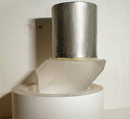
The professional optical workers have used a number of fixatives and epoxy type resin adhesives to hold prisms in their cages, whilst in aligning jigs, so when the adhesive sets the prism is perfectly collimated. We can do the same using Araldite or similar. A short piece of tubing will have to be machined, or acquired that will push comfortably over the objective. If the tube has been faced square where the prism is to be bonded, no jigs will be required and the two can be bonded together accurately: -
On the left is the finished tube slipped over objective.Note the almost flush edge of tube and front element to utilise maximise working distance.
Tube on right "Araldited" to the prism, and nestled nicely into a roll of PVC tape whilst curing for 24 hrs.
The device must reflect the light through exactly 90 degrees to provide distortion free imagery, whether a prism or mirror is used is not important, the 90 degrees are. But providing the bottom end of the tube is square, all that is necessary is the keep the two components together until the bonding is firm. Resin type adhesives can be very messy and care is required not to get adhesive on the glass faces where the imaging light is to pass through as this will be difficult to remove once the bonding agent has hardened. Make sure that the prism face is level whilst the adhesive is curing otherwise the tube will slowly but surely slide askew.
When finished, the device can be painted, and given a matt black coat over the non functioning faces of the prism to reduce unwanted light entering and reducing contrast.
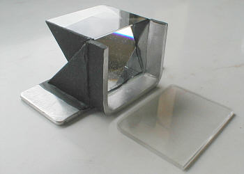
Prism mounting.........for Method B
This is somewhat easier to construct in that no machining is necessary, but needs a larger prism, because being part of the cell wall the specimen needs a little 'room' for comfort.
Two small alloy plates can be bonded with "araldite" as shown to support the prism, but if you'd prefer another method of support, remember that the 45 deg angled face must be left free for cleaning purposes, as any greasy streaks will impair the images. Important too, is that no adhesive must be allowed on this 45 deg face as this will inevitably form part of the optical face of the prism and simply ruin the imagery. Ideally this face should be covered or masked from the effects of unwanted external light. The only important alignment when 'gluing up' is that the upper face of the prism be dead parallel to the stage, although in practise it might be more convenient to use a small 90 deg. L square to make sure the vertical face of the prism is at right angles to the stage, which amounts to the same thing.
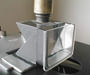
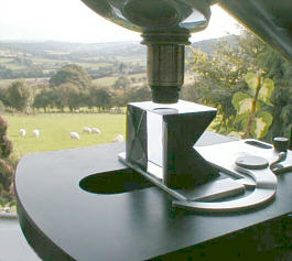
I decided to keep the prism stand open, allowing easy cleaning of the optical surfaces. Here the stand is made from alloy plate 'Araldited' to the edges of the prism and the base. The triangular supports were bonded first, then trued up with a file, checking for level by placing on the stage and lowering a large objective with wide front element mounting, which when lowered carefully very close to the upper surface of the prism, revealed any deviation from parallel. Once this was accomplished the base plate was bonded on. A U shaped strip of alloy was fashioned and bonded to the outer edges of the glass/alloy face as shown on the right, and the thin plastic 'window' which is temporarily stuck to the U face using vaseline jelly, completes the prism/cell unit. Painting the surfaces that have no optical function with matt black is necessary to reduce glare from unwanted light scattering around inside the prism.
General Tips.......Illumination
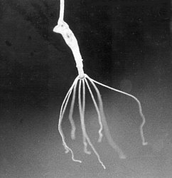
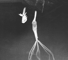
The way the cell is illuminated is important, and although we can source the light into the cell directly as in brightfield, it would be more satisfying and technically superior to arrange side or overhead lighting to provide a semi darkground image. In this way more detail is made visible and promises spectacular views of Hydra using its tentacles for feeding etc..
Young Hydra takes on a Daphnia !
Overhead lighting.
Illuminating the specimen in the cell should not be difficult. An easy and controllable method is to use external sources independant of the microscope, which can be directed from any angle; 'cold light' fibre optics come into the arena nicely for this and an ingenious worker might use dimpled aluminium foil to scatter light around the subject etc..
Miscellaneous items
The cover glass thickness correction for a 2" objective has to be ignored in this situation with about 1.5" of glass prism to pass through!! Far more important in this situation is contrast reduction and flare caused by lack of cleanliness of glass surfaces.
If your selected prism has unwanted** aluminium coatings, they can be removed by using either dilute hydrochloric acid or caustic soda. There is no need to physically aid the process by rubbing which will inevitably result in marking the surfaces, then finally rinsing very throughly in water and tissue drying will do fine. Dissolving caustic soda crystals ( sodium hydroxide ) in water evolves much heat and can crack glass prisms with ease, so allow to cool somewhat first and keep fingers out of the concentrated solution too. The evolution of hydrogen gas should not be a hazard given that the mass of aluminium removed is tiny.
** If the diagonal face is aluminium coated , leave it be.
Other Uses
Looking at specimens of living Hydra going through the 'motions' etc. is well worth pursuing, but we can use the prism techiques for other subjects too:-
Imagine forming a tiny water drop hanging from the tip of a hypodermic syringe which is teeming with aquatic life ?............and observing that tiny self contained world held together by surface tension ??
Concentrated salt solutions can be suspended as a drop to evaporate and crystallise in situ ??
---------------------------/\------------------------------
Pro's
1) Simple and definitely DIY capability of observing vertical cells.
2) Use of existing 'scope.
3) The ability to photograph/ccd movie/video living specimens using existing camera setup/attachments
4) Method A setup can make use of an objective with a larger working distance than the limb can cope with.
5) Fairly quick to setup and take apart.
Con's
1) Takes time to get use to controlling movements of cell etc..
2) Can be virtually impossible to setup on small 'scopes with limited vertical movement of coarse focusing etc..
3) Though not stereoscopic, the images are best appreciated using 'scopes with binocular heads.
4) Availability of suitable prisms ??
 |
| Comments welcomed to Paul James. |
Published in the November 2000 edition of Micscape Magazine.
Please
report any Web problems or offer general comments to the Micscape Editor,
via the contact on current Micscape Index.
Micscape is
the on-line monthly magazine of the Microscopy UK web
site at Microscopy-UK