A Miniature Variable Compensator.
For the older
microscope stands.
By Ian Walker. UK.
Introduction.
Earlier this year I described a
simple home made variable compensator for use with crossed-polars to
make
measurements with thin rock sections and provide an insight into the
workings of commercial Berek style compensators at a tiny fraction of
the cost of those from Zeiss, Leica et al and is shown below in Fig 1. below. Using a
finely cleaved piece of mica the unit is situated on the microscope
base between the light source plus polarizer and substage. Well that's
fine I thought to myself I was pleased with the results and the overall
design but I wanted to take it one stage further and make it available
for older microscopes which use an angled stand and external light
source. To make it viable it was going to have to be a light
self contained unit with the only likely option of fitting it to the
eyepiece tube this demanded a novel approach.
Further information on the parts and materials of
the original compensator can be found by following the link at the end
of the article.

Fig 1.
Original compensator - a heavy base design for a
Zeiss microscope with built in illumination,
flat base and horizontal stage.
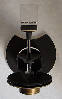
Fig 2.
Top view of the original compensator.
The idea of this article is not to give detailed instructions,
measurements and
materials of the unit I have built, but the concept which can be adapted
to whatever
microscope you might like to use and materials you have to hand
including any of your own improvements
you wish to make. Ideally you first choose a favourite low power
objective in this case my Swift 1" achromat and set the microscope up
for optimum contrast with the condenser iris and then fix the unit in
position, you could then use other objectives but you will need to know
where you normally set your condenser for the higher or lower power
objective since you do not want to be continually removing the
compensator from the tube to allow setting of the condenser. It is
worth
making a prototype for your own microscope to find whether it is
feasible for your stand, the main point being sufficient eye relief.
However I find both the 5x and 8x eyepieces for my Swift
stand work well even though the uppermost part of the compensator
stands several mm away from the eyepiece although
your eye must be held very close to the compensator.
Why use a variable compensator?
The first thing is, I and
am sure many others, would like to emulate to a certain extent those
accessories normally reserved for the very few and fortunate folk in
laboratories who can use extremely expensive Berek and other
variable compensators. Unlike fixed compensators such as the 1/4 or
full wave plate
the variable compensator can provide a range of interference colours
which can be useful in familiarizing oneself with the Michel-Levy chart
and see for real the colours that are normally reserved for books and
which are
nothing short of amusing in the variations of print quality. I have
several books with the Michel-Levy [birefringence] charts and they
differ enormously; so
much so it is difficult to know which to trust. You can also do simple
experiments determining the birefringence of a mineral in thin section
by canceling out the colour and measuring the figure on the
compensator, this is detailed in my last article.
Prototype for a miniature
compensator.
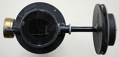
Fig 3.
The prototype was made from card cut by a compass cutter
with additional
low slung counterweight to improve stability, left to right is approx
7.5cm.
To allow the idea to come to fruition
I used a working prototype which could be modified to include
improvements as I used it in practice and found any shortcomings. The
main problem for the prototype is the likelihood of the unit falling
off the eyepiece
tube and with the unit only weighing 10 grams but with the
measuring disk to one side, the centre of gravity tends to pull it off
the tube, so I included a small brass counterweight to compensate which
worked well. As with my previous design I used a thin cleaved piece of
mica which rotates about its axis to provide different amounts of
compensation introducing the various interference colours from lower
first to mid order second in distinct bands, the colour bands are much
more clearly defined than my first design probably because the mica is
so close to the eye. The various parts are held together by glue stick
and rubber
solution allowing them to be dismantled to a certain extent and
re-assembled to include new
ideas. Some of the parts are from an old video recorder including the
steel spindle running from the mica plate to the adjustment disk and
the grey plastic bearings are from transistor insulators. A possible
source of mechanical parts for projects like this are discarded 3 1/2"
and 5 1/4" floppy drives and CD drives from desktop computers where you
will find a number of small parts from the mechanism which may work.
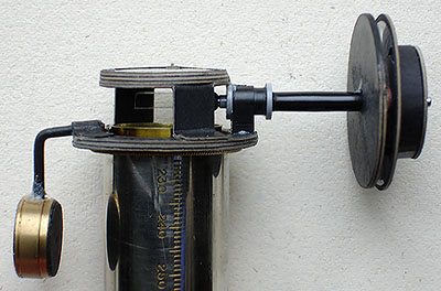
Fig 4.
A side shot showing how it fits to the eyepiece tube, eyepiece removed.
In Fig 4. you can see how the
prototype is built up from layers of thin card glued together to
increase strength and
stability. The lower disk fitting around the eyepiece tube is a
precision fit to accurately centre the unit on the microscope. The
cheap polarizing disk forming the microscope analyzer [available from
Knight Optical UK] is temporarily glued into place on the upper ring
with spots of rubber solution easily removed when
necessary. The picture gives an idea of the close tolerances between
the various parts and eyepiece tube. The length of plastic tube to the
rotating
measuring disk is calculated to allow sufficient clearance not to
interfere with the face when in close proximity to the unit. A delicate
touch is required when adjusting the unit so as not to displace it off the
microscope. Incidentally the inverted 'L' shape black plastic holding
the grey bearings is a small section cut from the cable retainer
found in a very old household 13 amp plug [these normally have the two
screws passing through it holding the cable into the body of the plug
but sadly the more modern ones are flimsy affairs]. However in the last
year or two plugs in the UK have become molded and no useful parts, it
worked so well it
was used in the final version.
The improved and final
design.
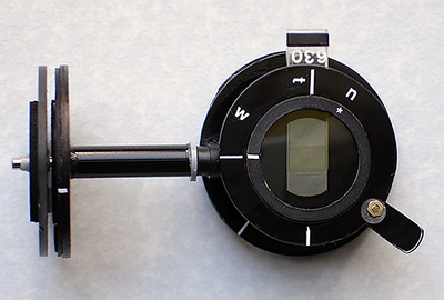
Fig 5.
View shows calibration marker on lower ring for aligning
unit to eyepiece
tube and additional 630nm compensator in situ. Top ring
maybe swung-out.
For stability the final design main
components are made from perspex which gives the unit much longer life
and
more stable operation than card unfortunately I have no easy way of
cutting accurate larger circles in perspex so I have to do it by
drilling a number of small holes neatly around the required hole size
snapping
it out and finishing by hand as shown at the end of the article
in Fig 18. The
compensator shares a number of
concepts from my previous design including the measurement scale built
around a small disc shown on the left hand side of Fig 5. A very rigid
plastic tube holds this fixed disk in position with its calibrations
allowing the steel spindle to rotate within when moving the free disk
far
left. The analyzer
is fixed uppermost on the unit whilst a sufficiently wide window
accepts the additional
compensator below it without interfering with the field of view looking
at the
subject. End stops on the calibration disk prevent the mica rotating
more than 90 degrees.
Once the perspex has been cut and filed completely round I applied a
thin coat of
black gloss spray paint to give a nice finish and allows the various
calibrating markers shown in white Letraset decals to stand out. A thin
slice of Knight Optical full wave compensator cut to the right
dimensions and orientation allows an addition to the variable mica
plate
plate to allow measurements up to third order
increasing its versatility over my previous unit.
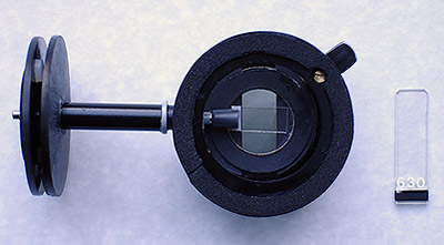
Fig 6.
Bottom view of unit showing foam base and additional 630nm compensator.
Fig 6. shows the 2
mm thick
high density foam which grips the eyepiece tube
flange firmly on my stand but allows slight rotation to allow the unit
to be aligned accurately in conjunction with the microscope polarizer
to give optimum
extinction, this could also be achieved by rotating the eyepiece tube
with the unit in position if
free movement is available on the stand. The mica plate is held by a
small rubber cup with a sharp knife cut to accept the plate and it is
not
held in place by
any adhesive. The additional full wave plate which is a slide fit is
held
by card rings cut in the correct size and orientation as shown above.
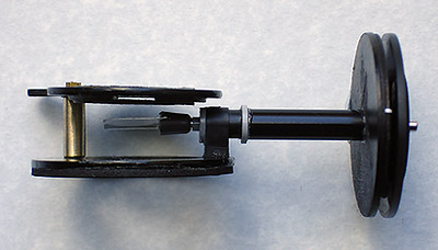
Fig 7.
Side view showing mica plate and slot for additional
compensator plate above.
Fig 7. shows the sturdy
brass
pillar holding the two perspex rings apart this has a long brass screw
running
through it fixing the two together however a nylon washer allows free
movement
of the upper ring holding the analyzer and additional compensator to be
swung out of position and together with the mica plate in its vertical
position allows normal viewing of subjects. This picture also shows
clearly the additional compensator slot in the top ring in this case
end on.
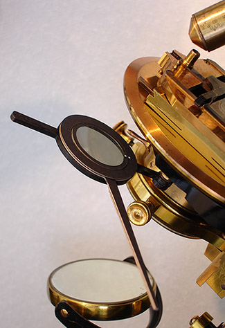
Fig 8.
Home made polarizer mount with long arm facilitates optimum
alignment in E-W direction with a known source
shown in Fig 9.
Fig 8. shows the matching
Knight Optical polarizer
swung out of its normal position on a mounting ring with a long arm
allowing rotation in the closed position beneath the condenser to
provide optimum extinction with a known polarizing source such as the
Zeiss Jena eyepiece unit set up N-S shown in Fig 9. Once we know that we
have the polarizer accurately set for E-W and analyzer N-S measurements
made with the compensator set for 45 degrees to the polarizer following
standard petrological techniques. I go through this procedure every
time the compensator has been off the microscope to provide optimum
results only taking a few
seconds to check. The home made mount shown above allows quick removal
of the centre polarizer disk to take dark-field stops, rotatable colour
Rheinberg rings stackable with the polarizer if desired to give
different hues and plain green and blue acetates.
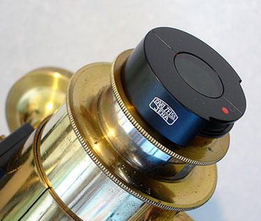
Fig 9.
A known source such as this Zeiss Jena analyzer is used to
accurately
orientate the polarizer in Fig
8
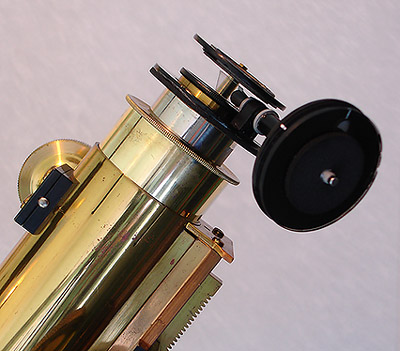
Fig 10.
Overview of the compensator fitted to an old Swift stand,
the design
relies on accurate friction fitting of the unit to the eyepiece tube.
Fig 10. shows the home made
compensator fitted to the microscope in its normal operating position,
the eyepiece tube has been purposely pulled out by about 10mm to show
the unit is stable without resting on the flange of the main brass gear
tube
assembly below but the design was based on the tube being normally
closed. One important point which is not clear in Fig 10. is that the hole
drilled in the base ring of the compensator must allow the eyepiece to
pass through, the compensator is gripping a small knurled flange about
2mm below the eyepiece as seen in Fig 9. which is part of the
design of my particular microscope. This is why it is important to look
at your own microscope for some time make a prototype and adapt the
compensator to fit your own needs. It was common for Victorian and
Edwardian brass microscopes to have these larger flanges just below the
eyepiece which is a convenient place for the unit to rest and grip.
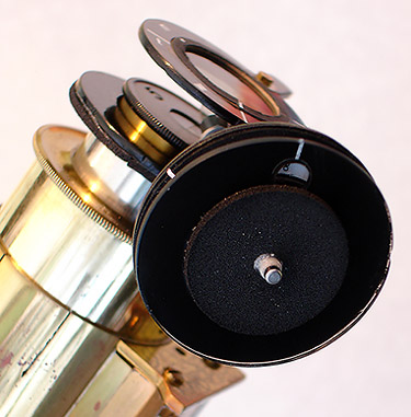
Fig 11.
Perspex adjustment ring and window, retardation calibrated in
nm.
A nice shot of the compensator is
shown in Fig 11. here
the analyzer can be clearly seen on the uppermost perspex disk held in
position by a friction fit card ring. The rotating and measuring disk
looks unnaturally large here being a macro shot and distorted
perspective. The perspex rotating disk is accurately drilled to be a
friction fit on the steel spindle but due to being only
1.5mm thick requires a stabilizing dense foam disk which also doubles
as a comfortable and convenient point to rotate the disk.
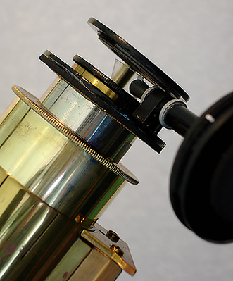
Fig 12.
Close-up of the mica plate showing the close tolerances
requiring accurate cutting and measuring of parts.
Fig 12. zooms in
on the mica showing the very close working distances between the
rotating mica and
the top of the eyepiece together with the lower face of the card
holding the additional compensator.
The 'L' shaped black plastic bearing holder carefully sawn from the
cable retainer mentioned earlier
can be seen together with the two grey bearings made from transistor
insulators the two together giving a smooth damped feel to the rotation
of the mica.
Results.
I must stress that my compensator is specifically made for visual
observation [your own could be more rigid and improved] since the
structure is not strong enough to hold the weight of a digital camera
also the camera would need a zoom of 4x with my eyepieces to remove
vignetting but for demonstration purposes I have taken some sections
from the standard circular field of view using a hand held digital
camera sitting lightly on the unit. This gives an idea of the colour
range obtainable, Figs
14-15-16.
were taken without the additional 630nm fixed compensator. Fig 17. shows a limited
view with the 630nm plate in position extending the compensating range
to third order. The minimum compensation of my compensator is around
250nm [1st order grey-white on the chart] but this could be adjusted
depending on the properties of the mica sample but with the mica in the
vertical position most of the original subject can be seen without the
effect of the compensator.
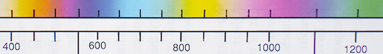
Fig 13.
Typical section from a printed birefringence chart for reference below
with some of my own rulings.

Fig 14.
With the mica almost horizontal in the light path the lower order
interference colours can be seen.
Crop from the camera set at 2.4x optical zoom, now we will increase the
angle of mica in Fig 15.

Fig 15.
A very distinct set of colour bands is seen from 1st order
yellow 400nm to 2nd order blue 700nm.
Colours depend on the angle of mica in the light path, a crop
from the camera 2.4x optical zoom.

Fig 16.
Zooming into the colours, 1st order deep orange 500nm to 2nd
order blue 750nm.
Close crop with the camera set to 3x optical zoom showing smoother
gradations.

Fig 17.
Using these colours together with a Michel-Levy chart we can do
experiments with thin sections...
Crop from camera 3x optical zoom, +630nm compensator giving 3rd
order 1130nm to 1300nm.
And finally, some of the
tools and parts.
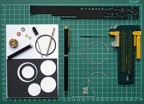
Fig 18.
Some typical tools and materials that went into building the miniature
variable compensators.
Plastic tubing, circular cutter, perspex, small drills, parts from an
old video recorder, card and foam etc.
Conclusion.
The
compensator can give older biological microscopes including Edwardian
and
Victorian stands fitted with rotating stages and external light sources
the chance to be used as interesting polarizing microscopes with a hint
of the exotica
normally reserved for the modern dedicated polarizing stands
costing more often than not several thousands of pounds. Small parts
like the transistor insulators [the same design also used for 1 amp and
3 amp low voltage DC regulators] are most likely still available from
large electronic component suppliers online like RS, Farnell, CPC or
Maplin in the UK. However with a little ingenuity from your own
'bits-n-bobs' around the house no surplus electronic parts are needed
in the main construction such as the bearings for the spindle just a
source of material suitable for the compensator plate.
Comments to the
author,
Ian
Walker,
are welcomed.
Reference.
A
variable compensator for microscopes [My original and larger design
written for Micscape earlier in 2006, this includes more detail on mica
and experiments with thin rock sections].
Related
articles
Notes on mica in the light train of a
transmitted polarized
microscope
- Gordon Couger provides some valuable
notes on sourcing and cleaving mica for homemade compensators in his article
in the November 2006 issue.