EXPLORING THE POSSIBILITIES OF SINGLE LENS
MICROSCOPES
By: Alvaro Amaro de Azevedo - (Brazil) 10 September 2005
1. INTRODUCTION
Some previous relevant works about this subject have already been published in the last few decades and I shall mention the research by Brian J. Ford(1) who demonstrated the amazing high quality images, which can be obtained by the single lens microscopes made by Antonie van Leeuwenhoek (1632 - 1723). It's clear at this point that despite the apparent crudeness of their construction, from the optical point of view, a tiny glass ball can work as a lens with enough clarity and resolving power in order to render satisfactory imaging. The image, despite the spherical aberration, was by far superior to any existing microscope made by his contemporaries. As a matter of fact lens manufacturing techniques would have to wait for another 150 years to reach the same level and eventually surpass it.
In
the Museum of Utrecht (Holland) there is still one of the nine
surviving original pieces made by Leeuwenhoek. This model is
able to magnify up to 270X. This achievement might be thought
as the highest practical magnification obtained by using a
single lens microscope. However, theoretically we know now
that the shorter the focal length (f) the greater the
magnification. As magnification is the result of the division:
250 mm/f (mm), thus we come to the conclusion that if f = 0,5
mm, the lens should be able to magnify 500X. Some questions
then came to my mind: can such a lens be built with readily
available materials? Is it possible to obtain images out from
it? Are these images good enough to observe? Are they
comparable to those from modern compound microscopes? What is
the maximum real practical limit of magnification using a
system with a single lens? The quest for these answers led me
to carry on my own research and this is the subject of this
article.
2. REPLICATING LEEUWENHOEK'S MICROSCOPE
I couldn't start without trying to make a replica of a Leeuwenhoek microscope, which is very well described by Alan Shinn (2). For this trial, I made a ball lens 3 mm in diameter using a good quality crystal glass rod. I got almost all what I needed for the construction in the local shops and after some attempts, I could make a model yielding roughly 100X.
On the tip of the pin, where the specimen should be mounted, I
placed the head of a housefly. The specimen was adjusted to be
focused on the mouth parts. Under the adequate illumination,
it's possible to see the hair-like structure coming from the
proboscis
. This organ works like a sponge absorbing the liquid
resulting from the contact of its digestive enzymes and the
food where it landed. The image is remarkable, but it is
greatly affected by the short depth of field that makes it
blurry in the most parts of the image out of the focal length.
However, if the specimen is flat and placed over a thin plate
of glass (slide cover) stuck on the holding pin, then it's
possible to see that the image is surprisingly good, except at
the borders of the field.
3. MY FIRST MICROSCOPE MODEL
After
seeing the image that such a construction permitted me to
obtain, I started to plan how to construct a model able to
achieve higher magnification. I found useful information in an
article from Giorgio
Carboni
(3) where he describes precisely how to make the
whole set-up using easy-to-find materials and also giving
valuable tips to create glass ball lenses from ordinary glass
rods and some other extra lab materials. Using such
information, some thoughts and lots of sweat, I came out with
my first model which is represented in the diagram
below:
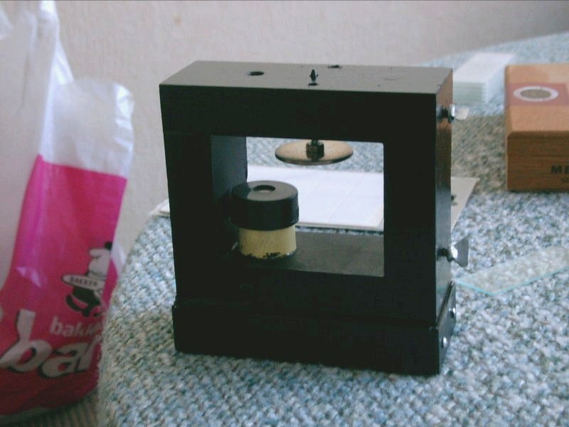
The material of choice for this model was hardwood. The instrument consisted of a frame of wood having a hole in the upper side. Underneath this hole, I placed an illuminator set, made of a photographic film cassette canister where a small light bulb was held. The bulb was powered by a set of batteries placed inside the lower part. The circuitry included a switch to turn the bulb on and off. On the upper side, I placed two clips to hold the slide and finally I added the “L” shaped plate that held the lens. Below this plate there was the focusing screw that was made from an ordinary 1/8” x 2” screw and a drilled coin (focusing wheel). The whole set was coated in opaque black paint as showed in the picture below:
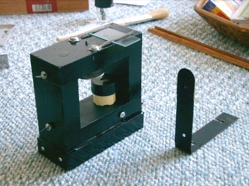
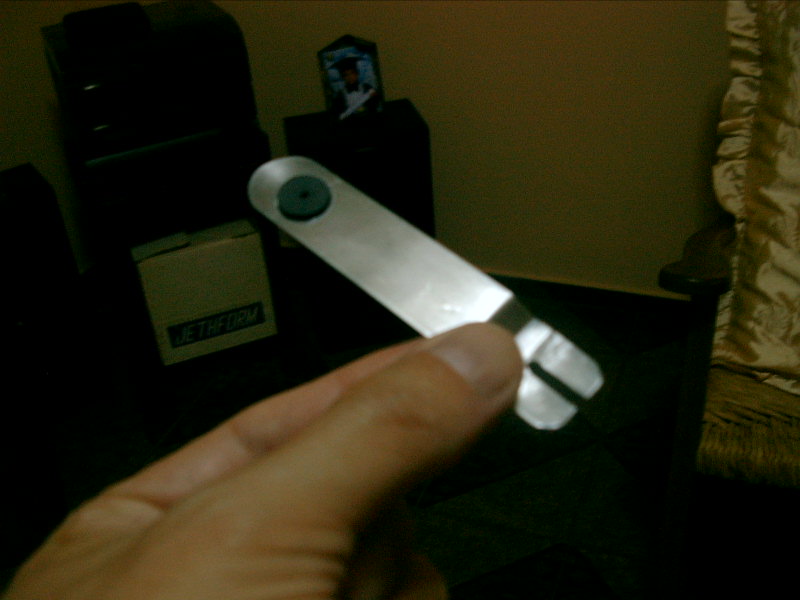
The ingenious aspect in this model was the design of interchangeable lens set-up. The “L” plate that is easily removed from the frame through two screws holds the lens, which is actually lying over a seat fitted underside of this plate. If the lens needs to be replaced, the seat is easily removed and another seat can be fitted. This arrangement, allows switching lenses from a wider variety of magnification if necessary.
The lens mounted in its seat. The “L” shaped support
In this original version, the lenses once in place were unprotected and dust landing could easily impart the overall quality and definition of the images. This problem was to be solved only in the second version, which will be presented later on. Basically, the design worked quite well and many specimens were observed under different magnifications. This model was capable of yielding high magnification images but was limited by the lower efficiency of the illuminator.
4. IMPROVING THE DESIGN AND FEATURES
Once all possibilities were fully explored, I thought that it was necessary to make a new design in order to solve some mechanical problems and also verify whether a higher range of magnification was yet possible to achieve.
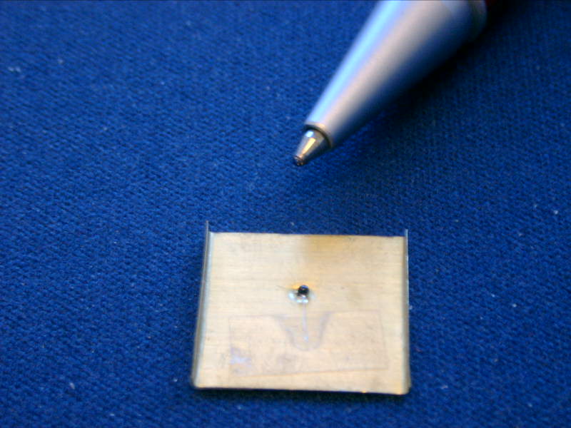
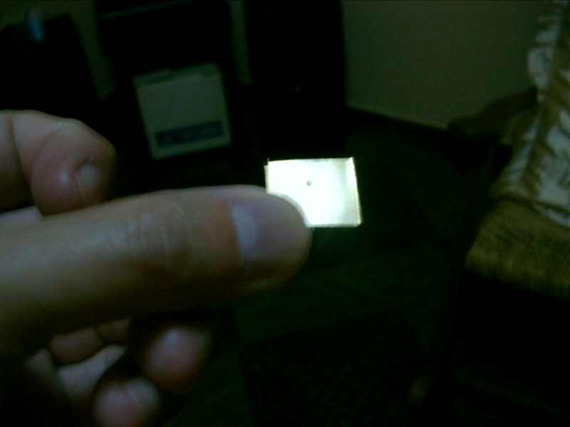
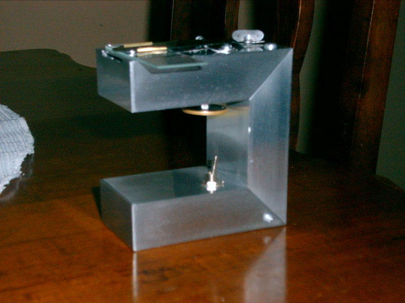
This time, I have chosen to make the structure of the instrument in a “C” shaped frame made of hollow aluminum rule used in building construction. Each side is 10 cm long, 5 cm wide and 2 cm thick. Inside this frame there was room enough to put a set of four penlight batteries, a switch and wiring to power a white LED placed in the upper side. A diaphragm was placed between the LED and the aperture in the upper side. The top of this part became the stage by placing two clips to properly hold the slide. Then the lens support was made from a carbon steel plate pierced 1.5 cm far from the tip. The width of the hole was 1 mm. Below this metal plate I placed a focus screw whose tip was ground to a conical shape. The lenses were held in metal seats, likewise the first model.
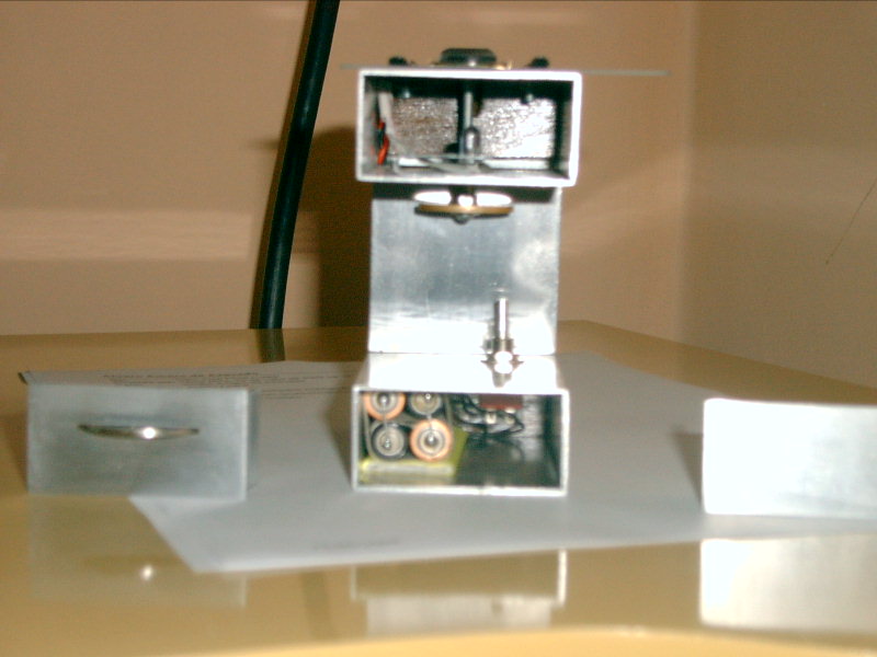
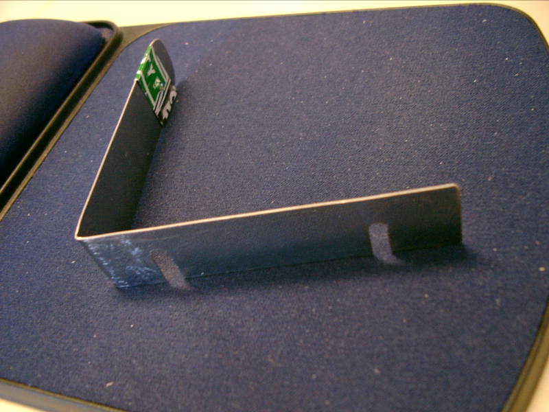
To overcome dust landing over the surface of the lens, I managed to place a cover in the top of the holding plate. The cover however was a small lens taken from an old microscope objective. The small lens however has some 10 mm focal length what means that it doesn't work actually as a lens but rather as a protection.
Because
the illuminator was brought much closer to the stage it was
rendered more efficient and allowed me to obtain higher
magnifications. Nevertheless, this wasn't by far the most
astonishing finding I have made when building this piece. I
was trying to find a more efficient way to homogenize the
light without losing the brightness. Using translucent filters
between the LED and the slide didn't seem to work well as the
brightness was jeopardized and the contrast went very bad. I
tried many, many different media and finally I discovered that
if
the finest dust recovered from filing an aluminum block was
appropriately spread over a transparent adhesive sheet this
would work much better. This simple arrangement greatly
improved the contrast without imparting significantly on the
brightness. The combination of correct aperture, absence of
air bubbles, adequate cleanliness and optimization of the
illumination system, showed that the image can reach a level
of quality not thinkable before.
5. SEEKING THE PRACTICAL LIMITS
Observation
when using higher magnification lenses is rather more
difficult. I could not use ordinary slide covers as the
thickness usually exceeded the distance necessary to attain
focus. Then I had to find out a way to overcome this practical
obstacle. This was achieved by using ordinary transparent
polyester sheets that have proven to yield reasonably good
results. To understand what these set-backs are all about we
have to take a look at the dimensions that are involved. For
higher magnifications, the lens focal length is small,
e.g 0.5 mm if it was possible to achieve 500x. However
the smallest lens I made was 0.33 mm thick and this means that
the radius from the ball is 0.16 mm. Therefore, the
clearancegap between the specimen and the lens surface can be
fractions of a mm. Ordinary cover slips are 0.10 mm thick,
therefore it would be increasingly difficult to reach the
focus distance as the lens may not be able to be brought close
enough to the specimen. Polyester films as thin as 0.05 mm
works perfectly for this purpose.
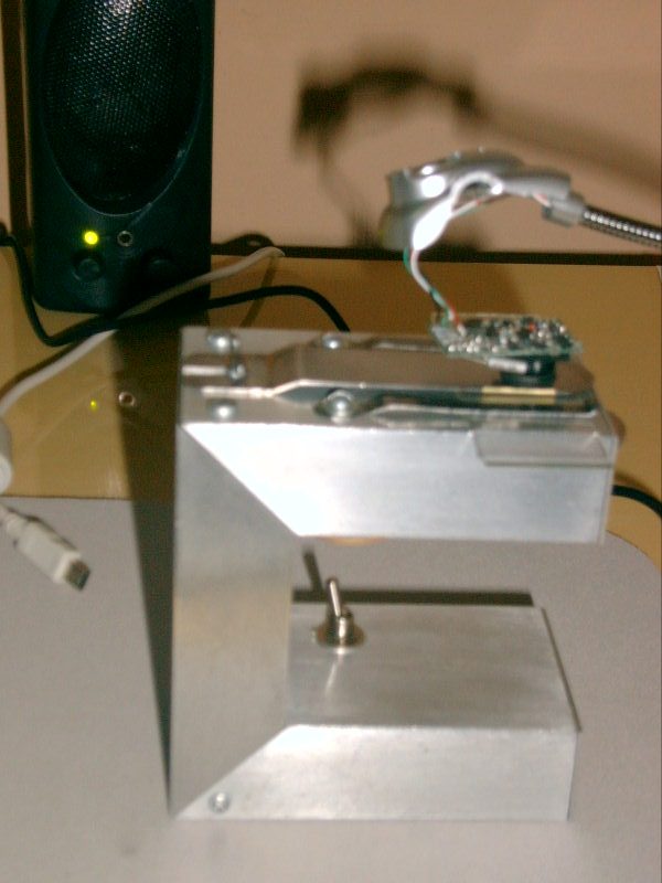
6. CAPTURING IMAGES AND RECORDING SET-UP
For capturing images and obtaining the pictures, I made a simple adaptation. I bought a low budget web cam and unscrewed the lens. Then I placed the camera in the top of the aperture where the ball lens is mounted and focused by looking to the image generated on the screen of the computer. Once the image was focused accordingly, I captured the image from a variety of specimens that my curiosity took me to observe. In the picture below, I show how the arrangement of camera and microscope were put together.

The set-up as it was displayed above, also allowed me to record small movies from slides in which living microorganisms were swiftly moving in all sorts of odd motions, sometimes in a very hectic activity as devouring decaying fruits or just gliding around a source of food. Despite the fact that bacteria are generally difficult specimens to observe due to their nearly transparent membranes, I noticed that the single lens microscope yielded a sufficiently contrasty image enabling to observe their behavior. Conventional microscopy would require staining techniques to render clearer imaging. In this case however, because the specimens could have been observed alive, it was possible to record movies and have a chance to study more attentively how these organisms moved and how they interact with the surroundings and with other co-existing species.
Highest Magnification Lens Details
Clearance = 0.09 mm
Radius 0.16 mm
focal length to be
determined
For lenses this small I was uncertain how to reliably measure the true optical magnification or focal length with facilities available to the hobbyist and would appreciate any suggestions from readers. Determining the resolution of known test subjects may be a more reliable indication of lens performance.
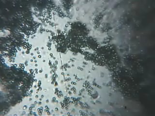
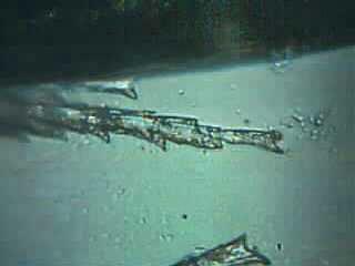
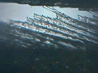
7. - GALLERY OF IMAGES
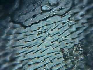
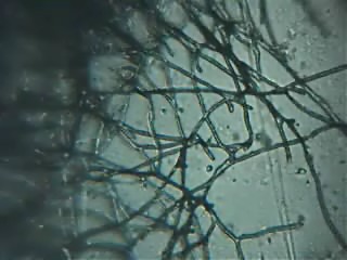
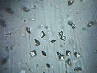
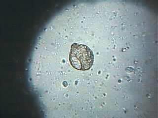
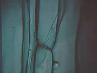
In this section, some of the images captured by different magnifying power lenses recorded along my research. The magnifications are approx. screen magnifications for a 15 inch screen which gives some idea of the performance of each lens made and optical magnification.
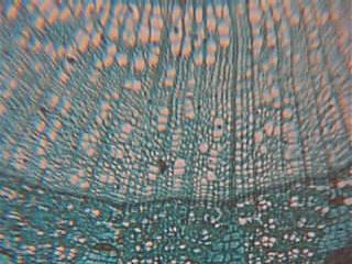
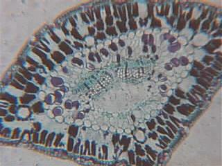
Tilia Stem Transversal Section 75 X. Pine Needle Transversal Section 100 X
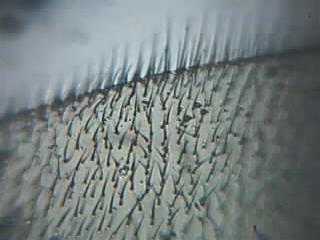
Housefly Wing 200 X. Housefly Wing 400 X
Green Mold Hyphae 400 X. Calcium Oxalate Crystals from Urine 400 X
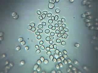
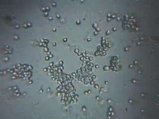
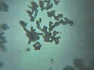
Red Blood Cells 500 X. Unknown Yeast 500 X
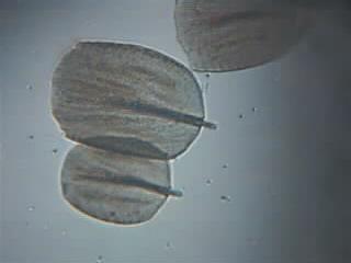
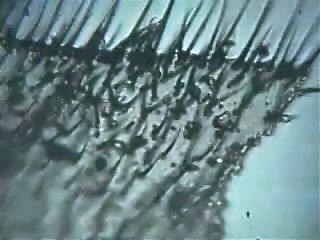
Unknown Organism 500 X. Butterfly Wing's Scales 600 X
Onion Peel Cells 600 X. Fig Tree Latex 600 X
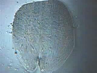
Pigeon Feather 600 X. Silverfish Scale 600 X
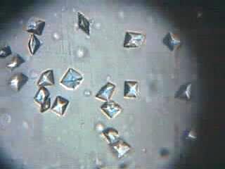
Pigeon Feather 600 X. Calcium Oxalate Crystals from Urine 650 X
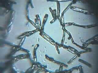
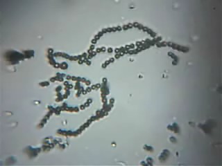
Green Mold Hyphae 850 X. Green Mold Spores 850 X
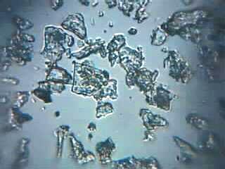
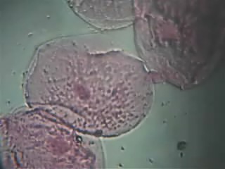
Talc Powder 850 X. Mouth Epithelial Cells 850 X
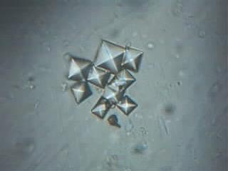
Housefly Wing 1000 X. Calcium Oxalate from Urine 1000 X
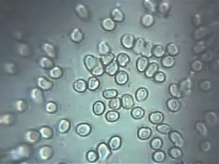
Red Blood Cells 1000 X. Green Mold Spores 1000 X
8. - FINAL NOTES
This research has shown me that single lens microscopes are definitively a viable tool for microscopy offering some advantages such as simplicity of manufacturing, easiness for carrying together in field exploration, ability for observing low contrast species like amoeba or bacteria and compatibility with recording cameras, among others. For amateur observation, it represents an opportunity to have a good quality imaging resource without the need to acquire highly expensive hardware. I would say that the possibilities for single lens microscopes are far from being fully explored, especially in these days when aspheric lenses are becoming available in miniature sizes and could strongly improve the overall image ridding it from the spherical aberration, which still represents the main drawback of this microscope if compared to modern day available resources.
Comments to the author
Alvaro
A. de
Azevedo
is welcomed.
Editor's note: The author shares further results with making higher quality and smaller lenses in this Jan 2006 Micscape article.
9. - REFERENCES
1. - The Leeuwenhoek Legacy, Brian J. Ford
2 . - To Make a Van Leeuwenhoek Microscope Replica - 5/16/96 copyright Alan Shinn
3. - A Glass-Sphere Microscope, Giorgio Carboni, January 1996
Published in the September
2005 edition of Micscape.
Please
report any Web problems or offer general comments to the
Micscape
Editor.
Micscape is the
on-line monthly magazine of the Microscopy UK
web
site at
Microscopy-UK
© Onview.net Ltd, Microscopy-UK, and all contributors 1995 onwards. All rights reserved. Main site is at www.microscopy-uk.org.uk with full mirror at www.microscopy-uk.net .