Robert R. Pavlis, Girard, Kansas USA
Polarising microscopes are often used in several scientific fields for studying crystals. Geologists use them so much that they are sometimes called "geological" microscopes. However, they are also widely used in chemistry and physics.
Polarising microscopes are used for quantitative precision measurement of crystals and of their crystallographic properties. Until the development of X-ray crystallography they provided essentially the only technique to determine crystal type.
Polarising microscopes have to be constructed rather differently than other microscopes for them to be able to carry out these functions.
 Perhaps the most obvious special requirement is two polarising filters. Modern polarising microscopes use special filters made from a strongly pleochromic material that only permits visible light with its electric vector oriented in one direction to pass through it. Earlier microscopes used Nicol prisms. One filter must be located below the condenser, and the other someplace between the objective and ocular. Both of these must be mounted in such a way that the direction of the light's plane of vibration can be adjusted by rotating them, and the rotation axis must have precision calibrations. (All of the beautiful colours so characteristic of polarising microscopes can be obtained by equipping ordinary microscopes with filters, but that would be completely inadequate for conducting the measurements possible with polarising microscopes.) The design of the instrument must also provide a simple way to remove the upper polarising filter from the light path for studying crystals that exhibit pleochromism.
Polarising microscopes must have a precision graduated rotating stage. Using them for crystallographic studies requires that angles be measured to fractions of degrees. Thus the stage must be made to high precision. This precision obviously adds to the cost of these instruments!
The requirement of a rotating stage implies another requirementthe objectives there must be a provision for centring them. Some polarising microscopes accomplish this by using special objectives with centring screws. Others incorporate centring screws in the microscope nose piece. This is an absolute requirement for these microscopes, so that specimens will remain on the field when the stage is rotated. No matter which of these schemes a manufacturer uses to accomplish this, the result is higher cost!
The index of refraction of crystals, except cubic ones, is different in different directions. In uni-axial crystals (tetragonal and hexagonal) there are two indices of refraction, and bi-axial crystals (monoclinic, triclinic, and orthorhombic) there are three. This means light passing through a crystal will have different velocities depending on its direction of vibration. Polarising microscopes need to have some means to observe and measure the relative indices in different directions in crystals. This requires being able to insert special wave plates into the optical path. (Compensator or retardation plates.)
Interference patterns are visible when looking into the optical tube of a polarising microscopes. These are very useful for determination of the crystal structure of the material. These interference patterns can be better seen by inserting a special lens into the optical path of the microscope. These are Bertrand lenses, and they are generally built into polarising microscopes.
The optical materials used in polarising microscopes MUST have uniform indices of refraction in all directions. This precludes using fluorite lenses in these instruments. The glass employed must be strain free, because strains result in uneven indices of refraction. Special strain free objectives and condensers are thus required for these instruments.
Many modern microscopes are only equiped with binocular heads. For a polarising microscope, however, it is highly desirable that there be available both a binocular and monocular head. The latter is particularly useful for use with a Bertrand lens, for high power observations of strongly coloured specimens, and especially for precision measurement of the angles of crystal faces. Of course there must be available oculars with reticles!
Polarising microscopes are fairly uncommon. It is generally very difficult to locate used research quality instruments of this sort because far fewer instruments of this design have been produced, and the ones purchased by research organisations tend to remain in research laboratories for decades.
New research quality polarising microscopes from the major microscope manufacturers are extraordinarily expensive. All cost substantially more than most new automobiles!
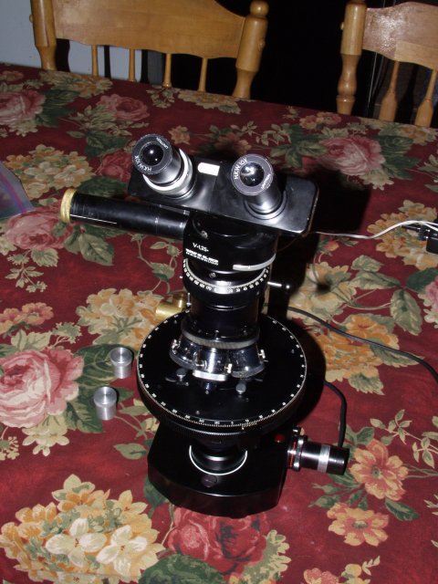
Recently I was able to acquire a Wild M21 microscope. This instrument is in amazingly good condition, especially considering that these microscopes were produced from about 30 to 40 years ago. It was provided with both a monocular and binocular head.
It came complete with a 4X, 10X, 20X, and 40x objectives. Wild polarising objectives have centring screws on the objectives themselves. All four of these objectives are in wonderful optical condition and the centring screws were in like new condition.
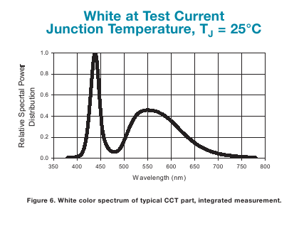
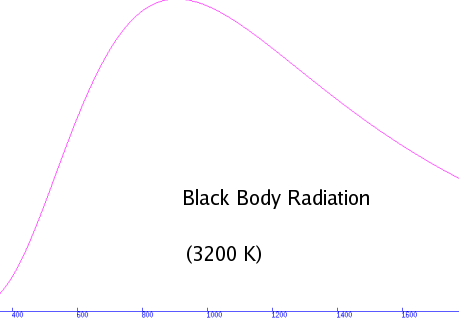
This Wild M21 also came with the original M21 illumination system, complete with transformer. After using it for a while I began to question whether or not it would not be better to build an illuminator for it using the new K2 light emitting diodes. I was very much aware of the fact that there are two negative features for these devices namely the peculiar weakness of radiation at about 480nm and a rapid fall off of radiation in the longer red wavelengths. The manufacturer's spectral specifications are shown below to the left. The distribution of radiation from a 3200 K light source is shown to the right:
The distributions are dramatically different! This could obviously introduce problems when trying to measure birefringence, which depends critically on observing colours. One must remember, however, that the tungsten filament lamp is a truly wretched light source. It provides far too little radiation at the short end of the visible spectrum and far too much at the long end. Filters are truly mandatory to reduce the red intensity. To make matters worse the short end of the visible spectrum practically disappears when the lamps are dimmed by decreasing the current flowing through them. The truth is that it is not a manner of deciding which type of lamp is better, it a matter of deciding which is least bad!
I discovered that these LEDs are much less expensive than the older 5 watt ones, and also brighter! I acquired mine before the "K2 star" type became available, and this required thinking about a different way to design an holder for them.
The image below shows the new style holder. Although it is a bit more difficult to fabricate, and requires more machining, it has certain advantages over the star LED type holder described earlier. I decided that I would use brass for this project, because the alloy that I had in stock is very easy to machine. The LED is secured to a 6mm aluminium square rod by epoxy cement which in turn is attached to the body of the holder with two 3mm screws. It would probably be a poor idea to use thinner material, because there would likely be heat transfer problems. I tried to get the layer of epoxy between the LED and the aluminium as thin as possible to improve heat transfer. I considered using 6mm square copper instead of aluminium, but I could not find any copper square rod available locally, so I used what I had available. I also put heat transfer paste beneath the aluminium bar to permit better heat transfer into the brass holder.
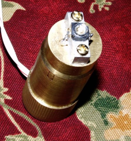
I took great care to build the part with extreme precision. Instead of simply running the wire down the centre of the brass body of the holder, I milled a slot on the end of the holder, and then attached a flat circular brass cap to the end of the holder with two 3mm screws. This not only made the holder look better, it also prevents accidentally applying to much pressure to the wires which could easily pull the wires loose from the tiny lugs on the LED.
The most difficult part of the project turned out to be soldering the tiny lugs on the LED! It is so tiny that some provision is needed to hold it whilst the wire is soldered to it. One must also carefully consult the manuals for this LED to know which lead is to be positive and which is to be negative!
Since I have been working with microscopes and adapting high power LEDs to them for some time, I now have a constant voltage power supply. I also have built a small portable battery supplied system that uses resistors as current limiters, as well as several that utilise electronic device power supply systems and added current limiting resistors. The latter is less expensive and seems to work perfectly.
As soon as I had the holder made, I was ready to test it. Although the LED is rated at 1500 ma, even at 500 ma it provides brighter field than the original 20 watt incandescent lamp with blue filter. I searched the chemistry laboratory for some compounds that would show strong birefringence, and decided to use hexaphenyl benzene for the first test compound. I kept switching between the K2 LED and the incandescent bulb, adding the standard blue filter each time I used the incandescent bulb.
It was apparent to me at once that there is a fairly dramatic different rendition of colours as a result of the peculiar spectral distribution of these white LEDs with their very strong blue emissions and as a result of the lack of much blue in the incandescent bulb (The blue filter used with the incandescent bulb was still inadequate to compensate for the lack of blue emission from it.)
The truly wonderful feature of the LEDs, however is that when the current was cut to the LED to decrease brightness the colours did not change at all, whilst the incandescent bulb became extremely reddish, even with a blue corrective filter.
The next step was to obtain images with the LED and with the original lighting system. I have one of the peculiar Wild "trinocular" photoattachment, and I used it with a digital video camera to take still images through it. (My digital still camera weighs far to much to put on this attachment, and the video camera makes fairly good still images.) I took several images, alternatively using the LED and incandescent bulb. I always placed a clear blue correction filter in the optical path with the incandescent bulb. The image on the left is the one from the tungsten incandescent lamp, the one on the right the LED.
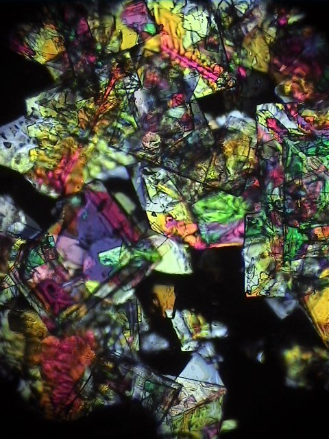
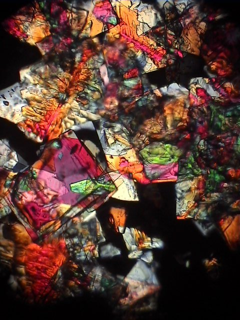
Even with the blue corrective filter the incandescent bulb images are very "warm". The LED images tend to be a bit too blue. Although the blue corrective filter + incandescent bulb image perhaps appears more visually pleasing, the LED image is really a substantially better approximation of the actual colours seen through the microscope.
After this experiment it became apparent to me that an ideal lighting setup with this instrument is to have both the incandescent lamp system and the LED system available for use at will. This realisation sent me back to the shopI made a special cap for the LED illuminator to protect the rather delicate LED at the end of it for the times when I have the incandescent bulb attached. A few minutes of time spent fabricating covers for delicate parts can prevent highly costly damage to optical and electrical parts!
Microscope manufacturers are beginning to incorporate more and more high power LEDs into their new instruments. Their greatest advantage is certainly the fact that their spectral distribution does not change when the power is varied. There are also two other advantages: LEDs to not get nearly as hot, because they are more efficient at converting electrical energy into light, and their emissive surface is generally more even than even the best incandescent bulbs.
After these experiments I quite strongly prefer the use of the LED illuminator. I am glad that I took care to machine the LED holder with the same precision that the Swiss craftsman used on the rest of the microscope decades ago. This holder will be on the instrument most of the time from now on!
All comments to the author Robert Pavlis are welcomed.
Microscopy UK Front Page
Micscape Magazine
Article
Library
Please report any Web problems or offer general comments to the Micscape Editor .
Micscape is the on-line monthly magazine of the Microscopy UK website at Microscopy-UK