by Mol Smith and Contributors at www.microscopy-uk.org.uk [visit?] plus various off-site
sources. (credited).
General
Microscopy is a term used to describe the practice of using a 'Microscope' (an instrument designed to reveal detail in objects too small to see with the naked eye) to study organisms and physical objects in greater detail. Until the 1600's (as far as we know), the idea that, things too small to be seen with the naked eye existed in our world and have a powerful influence upon our environment and the shaping of our reality, was a concept akin to a belief system because it could not be verified.
The first microscopes were 'optical' in nature - that is, they used glass lenses to magnify objects. Microscopical study and application no longer relies on purely optical magnification but instead has become a field of study assisted by 'microscope' instruments which use advanced techniques and exotic methods to probe objects and organisms with ever increasing levels of magnification. The branches of Microscopy can currently be divided into the following specialist areas:
Optical microscopy, which divides into a series of techniques which can be exploited using a glass lens microscope: Bright field, Oblique illumination, Dark field, Dispersion staining, Phase contrast, Differential interference contrast, Interference reflection, Fluorescence, Confocal, Single plane illumination microscopy and light sheet fluorescence microscopy,
Wide-field multiphoton microscopy.
Non-Optical Microscopy enables microscopes to use other techniques or probing electromagnetic waves (beams?) other than light to study objects and organisms. Light has a limit on magnification which can be achieved due to its wavelength. This means an optical instrument can only provide useful magnification up to about 1600x. Non-Optical Microscopy divides into a set of specialised techniques dependent upon the type of microscope employed: Electron microscopy, Transmission electron microscopy (TEM), Scanning
electron microscopy (SEM), Scanning probe microscopy, Ultrasonic Force Microscopy (UFM), Ultraviolet microscopy, Infrared microscopy, Digital holographic microscopy (DHM), Digital pathology (virtual microscopy), Laser microscopy, and Photoacoustic microscopy. These techniques are not discussed here as they lie outside of the scope and topics of Amateur Microscopy.
Professional and Amateur Microscopy
Microscopy itself is practiced by people involved with scientific research, by companies with applications in quality control and manufacturing processes, in medical and health application especially in clinical analysis and pathology, as well as in other different industries. All of these would be grouped into the term - professional microscopy.
But microscopy is also practiced fairly widely by people in a non-professional capacity, either for recreational reasons (a hobby) or for genuine independent research, often fuelled by personal curiosity. It should be noted that amateur microscopy enables research and the collection of knowledge regarding a wide range of organisms and processes which are of little interest to professionals or fail to be considered worthy of research budget allocation. It could be argued that the knowledge and observation
of single-celled organisms in fresh water and ponds, is greater by several magnitudes in the amateur domain rather than in the professional one. A simple compound microscope costing currently less than 100.00 UK pounds sterling, with glass lenses is all that is required for an amateur microscopist to engage in studying these and other living forms. A search in a web engine should reveal various organisations and publications as well as web sites which support and assist the amateur microscopist. These
information
sources are often denied early appearance in some search engines if you just enter the term 'microscopy' or 'microscope' due to the commercial focus on some of the world's main search engines.
History
The first microscopes were of a design which used rudimentary glass lenses to magnify light shone onto, or through, a target subject to make tiny details of its form bigger and more perceivable to the human eye and their considerations. [Read about the history of first microscopes?].
Our world, our universe, our very selves are not constructed of one thing. Each large object or animal is a combination of a multitude of different organisms, materials, and building blocks. Those components too are built of smaller parts. A Microscope enables us through different methods and different types of techniques to explore and examine what these parts look like and how they interact and integrate with other small 'blocks' of reality and ourselves.
A microscope might be considered to be a reverse kind of telescope. A telescope brings huge objects at extremely vast distances away from us closer, whereas a microscope enables minute objects at extremely close distances to be seen much larger than they actually are. Both instruments share a common trait: they reveal what is hidden from our everyday perceptions and senses. This helps us to understand their effects upon reality and its processes.
A replica of a microscope made by Antony Van Leeuwenhoek
[ How to make a replica of his microscope ]

An engraved drawing of Hooke's first microscope.
(Wiki commons licence)
Two notable early pioneers of studies using a microscope were Robert Hooke (1635 – 1703), an English natural philosopher, architect and polymath in the UK, and Antony Van Leeuwenhoek (1632-1723), a Dutch draper and scientist. Hooke used a compound microscope which had multiple optical elements whereas van Leeuwenhoek used single lens microscopes which he made himself. The single lens design was superior at the time to the compound microscope.
Hooke shared his studies in his famous illustrated book Micrographia published in 1665. Van Leeuwenhoek wrote letters describing and illustrating his observations especially to the Royal Society who translated them into English and were published in their journal Philosophical Transactions.
As is with all inventions and discoveries, it is highly likely that magnifying devices have existed for many centuries prior to the invention of the microscope. The earliest evidence of a magnifying device indicates a magnifying type of glass existed before 400 B.C. but may have been used more to focus the sun's rays for igniting wood than for observational study.
The invention of the microscope and its application in microscopy has transformed our understanding of the world, particularly in the field of medicine and disease control. It was used to verify that many infectious diseases were spread and caused by microscopic organisms (bacteria) too small to be observed with the naked eye. If you have a blood test, it is likely your drop of blood with be studied under an optical microscopy. Note: Viruses, which also are causes of disease, are many magnitudes smaller
than bacteria and can not be detected or observed by an optical microscope
The limitation of an average light microscope ( quality of the instrument may vary this only very slightly ) is to be able to resolve an entity 0.3 microns*2 across (300nm). Viruses are typically in almost all cases smaller than this. There are exceptions though! The smallpox virus is exactly this size - 0.3 microns (3 µm*3), and a unique viruses discovered in 1992 is a whopping size at 800 nm (0.8 microns): the MimiVirus! This is actually visible in a light microscope, although like a star in the sky to
an average telescope, it will be discerned as no more than the tiniest of specks. It is the largest known Virus, larger than some bacterium. It has been placed in a new family of viruses - the Mimiviridae.
A Description of the Various Fields and Techniques of Professional Microscopy
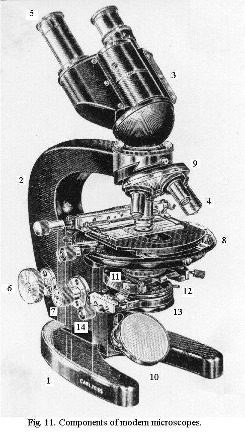
Optical Microscopy: Bright field microscopy is the basic microscopy illumination technique. A subject is placed on a stage8 beneath the magnifying lenses (an objective lens4 and an eyepiece lens5, and is illuminated by a light source from beneath the stage10. The light itself may be from an independent light source in the microscope or from an external light source which is reflected onto the underside of the
subject. It can be attenuated (made dimmer or brighter) and can be made to focus in such a way that more coherent rays travel up and through the subject and lenses to
enable better resolution and sharpness of image. This is accomplished through using a sub-stage condenser13 and iris aperture diaphragm12.
The image (right) shows a stereo microscope circa 1933 and its parts. All modern optical microscopes are still designed in a similar way and use equivalent parts. Bright field microscopy is best suited for studying semi transparent subjects, normally thinly sliced specimens mounted on glass slides. The resulting image is a light circle with a dark subject matter within - thus the term, 'bright field'.
Optical Microscopy: Oblique illumination is a method used to improve visibility and detail by increasing the contrast when studying low contrast subjects. A light is normally transmitting centralised light to illuminate a subject, but the light can be interfered with to accentuate any phase gradients within a transparent specimen. Oblique illumination also works well on single cells such as protozoa.
If you have a condenser and filter tray, A simple stop is placed in the condenser filter tray. This can be a simple piece of cut opaque card. The use of oblique (from the side) illumination gives the image a three-dimensional (3D) appearance and can highlight otherwise invisible features.

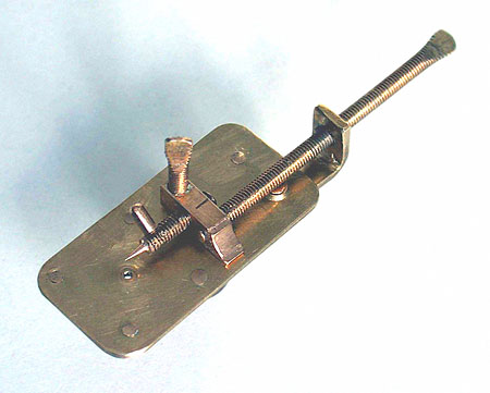
[Left] - A simple piece of circular card with a piece cut out (white) can enable effective oblique illumination for lower powers of magnification, typically 40x.
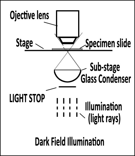
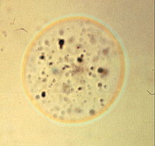
Optical Microscopy: Dark Field Illumination (also called Dark Ground) is a transmitted light technique that uses oblique light to illuminate the sample. A circular light stop is placed below the stage in the centre of the light illumination train (beam). The diameter of the stop is such that some light around its edge
passes up to the condensor and is refracted through the specimen. Light rays
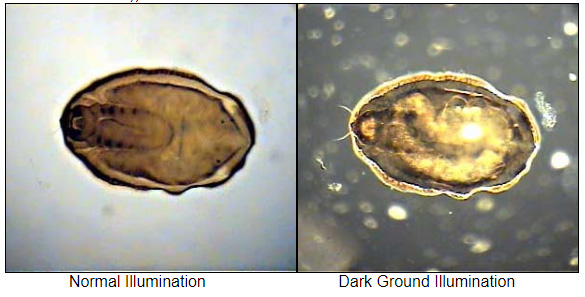
in the central part of the beam are blocked. Dark field can dramatically improve image contrast – especially of transparent objects – while requiring little equipment setup or sample preparation. However, the technique suffers from low light intensity in final image of many biological samples and continues to be affected by low apparent resolution.
Optical Microscopy: Dispersion staining. The optical properties of all liquid and solid materials change as a function of the wavelength of light used to measure them. This change as a function of wavelength is called the dispersion of the optical properties. The graph created by plotting the optical property of interest by the wavelength at which it is measured is called a dispersion curve. The dispersion staining is an analytical technique used in light microscopy that takes advantage of the differences in the dispersion curve of the refractive index of an unknown material relative to a standard material with a known dispersion curve to identify or characterize that unknown material. These differences become manifest as a color when the two dispersion curves intersect for some visible wavelength. This is an optical staining technique and requires no stains or dyes to produce the color. Its primary use today is in the confirmation of the presence of asbestos in construction materials but it has many other applications.
The most suitable set of liquids for general identification work is the Cargille set of Certified Refractive Index Liquids (HD 1/2). This comprises 31 liquids ranging from 1.500 to 1.800 at intervals of 0.010. A smaller set of the same high dispersion liquids consists of 16 liquids ranging from 1.500 to 1.800 at intervals of 0.020 (HD 16). For specialised analysis, eg. the identification of commercial asbestos minerals, set HD 6 is required. This consists of six high dispersion liquids: 1.550, 1.580, 1.605, 1.640, 1.670 and 1.700.ed
These are the colored Becke` lines of a glass sphere that matches the refractive index of the mounting medium at a wavelength of 589 nanometers.
(from
wikipedia)
The principle of dispersion staining, is an important analytical technique that can be used to identify many materials, though the technique is most commonly used for asbestos. This article contains two images that shows a special dispersion staining objective that is commonly used for this technique. Unfortunately these objectives are rather expensive. We describe here a much less expensive alternative!
The other author of this article, Jim Benko, pointed out that there is a way to utilise dispersion staining without purchasing a special objective. The technique that will be described is one that one would not want to use with an expensive high quality objective. However, it is possible today to purchase standard microscope objectives, generally made in China or India, for a few pounds or dollars. The dispersion staining objectives have a central occulting disk mounted directly behind the last lens element of the objective. There is a simple and inexpensive alternative!
The alternative is to place a small dot directly on the rear element of an inexpensive objective. The best material to make the dot is either India ink or, probably better, an oil based flat black paint or enamel. An excellent way to make circular dots like this is to use a small diameter circular wooden rod. Match sticks or round tooth picks can work very well. The dot needs to be at the exact centre of the objective, and it needs to be the correct size. Should one err in placing the dot, it can be "erased" using xylene. (Be careful to use xylene very sparingly so that it does not damage lens cements.)
Certain paints and enamels (such as epoxy and polyurethane ones) form cross links on curing. It is best to avoid these, because it can be difficult to remove them once they are fully cured. Many microscopists tend to have extra objectives lying around. This is an interesting way to provide an interesting use for them.
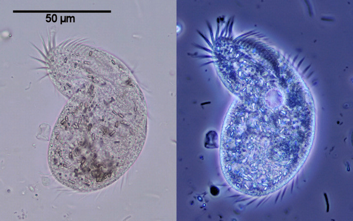
Optical Microscopy: Phase-contrast microscopy is an optical microscopy technique that converts phase shifts in light passing through a transparent specimen to brightness changes in the image. Phase shifts themselves are invisible to our naked eye, but become visible when shown as brightness variations, as our eyes repond to contrast difference. When light waves travel through a medium other than vacuum, interaction with the medium causes the wave amplitude and phase to change in a manner dependent on properties of the medium. Changes in amplitude (brightness) arise from the scattering and absorption of light, which is often wavelength-dependent and may give rise to colors. Without special arrangements, phase changes are therefore invisible. Yet, phase changes often carry important information.
Phase-contrast microscopy is particularly important in biology. It reveals many cellular structures that are not visible with a simpler bright-field microscope . Such structures were made visible to earlier microscopists by staining, but this required additional preparation and killed the cells. The phase-contrast microscope makes it possible for biologists to study living cells and how they proliferate through cell division. In the diagram right/top - The basic principle to making phase changes visible in phase-contrast microscopy is to separate the illuminating (background) light from the specimen-scattered light (which makes up the foreground details) and to manipulate these differently. The ring-shaped illuminating light (green) that passes the condenser annulus is focused on the specimen by the condenser. Some of the illuminating light is scattered by the specimen (yellow). The remaining light is unaffected by the specimen and forms the background light (red). When observing an unstained biological specimen, the scattered light is weak and typically phase-shifted by −90° (due to both the typical thickness of specimens and the refractive index difference between biological tissue and the surrounding medium) relative to the background light. This leads to the foreground (blue vector) and background (red vector) having nearly the same intensity, resulting in low image contrast.
In a phase-contrast microscope, image contrast is increased in two ways: by generating constructive interference between scattered and background light rays in regions of the field of view that contain the specimen, and by reducing the amount of background light that reaches the image plane. First, the background light is phase-shifted by −90° by passing it through a phase-shift ring, which eliminates the phase difference between the background and the scattered light rays.
Image on left - normal bright field. On right - Phase-contrast.
When the light is then focused on the image plane (where a camera or eyepiece is placed), this phase shift causes background and scattered light rays originating from regions of the field of view that contain the sample (i.e., the foreground) to constructively interfere, resulting in an increase in the brightness of these areas compared to regions that do not contain the sample. Finally, the background is dimmed ~70-90% by a gray
filter ring—this method
maximizes the amount of scattered light generated by the illumination (i.e., background) light, while minimizing the amount of illumination light that reaches the image plane. Some of the scattered light (which illuminates the entire surface of the filter) will be phase-shifted and dimmed by the rings, but to a much lesser extent than the background light (which only illuminates the phase-shift and gray filter rings).
Optical Microscopy: Differential interference contrast is used to image, living or stained specimens, which contain little or no optical contrast when viewed using brightfield illumination. The method is also known as Nomarski (DIC) microscopy, or mageNomarski and was invented by Georges Nomarski in the mid-1950s. In transmitted light DIC, light from the lamp is passed through a polariser located beneath the condenser, similar to polarised light microscopy. This polarised light then passes though a modified Wollaston prism (below the condenser) that splits the beam of light into two beams travelling in slightly different directions but vibrating perpendicular to each other, and therefore unable to recombine to cause interference.
The distance between the two beams is called the "shear" distance, and is always less than the resolving ability of the objective, to prevent the appearance of double images. The split beams enter and pass seprately through the specimen where their paths are altered by the specimen's varying thickness, slopes, and refractive indices.
When the parallel beams enter the objective, they are focused above the rear focal plane where they enter a second modified Wollaston prism which recombines the two beams at a defined distance outside of the prism. This removes the shear and the original path difference between the beam pairs. However, the parallel beams are no longer the same length because of path changes caused by the specimen. In order for the parallel beams to interfere with each other, the vibrations of the beams of different path length
must be brought into the same plane and axis.
This is accomplished by placing a second polariser (analyzer) above the upper Wollaston beam-combining prism. The light then proceeds toward the eyepiece where it can be observed as differences in intensity and colour. DIC microscopy causes one side of an object to appear bright (or coloured) while the other side appears darker (or a different colour). This shadow effect gives a pseudo three-dimensional appearance to
the specimen, but is not
a true representation of the geometry of the specimen, because it is based on optical thickness. The pseudo 3D appearance of the specimen can also be profoundly affected by it's orientation i.e. rotation of the specimen by 180 degrees can change a hill into a valley or vice versa. Therefore, DIC microscopy is not suitable for accurate measurement of actual heights and depths.
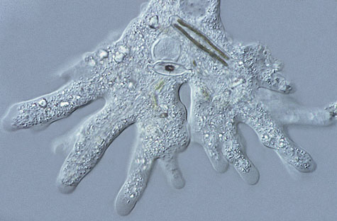
Example of a subject viewed using DIC microscopy.
These are numerous advantages in DIC microscopy as compared particularly to phase microscopy. Using DIC microscopy it is possible to make fuller use of the numerical aperture of the system because, unlike phase contrast microscopy, there is no sub-stage annulus to restrict the aperture, therefore, K�hler illumination is properly utilized. Images can be seen in striking colour (optical contrast) with a 3-dimensional
shadowed-like appearance and
at excellent resolution. Use of the full objective aperture also enables the microscope to focus on a thin plane section of a thick specimen without confusing images from above or below the plane (optical sectioning). There are no confusing halos, as may be encountered in phase images. DIC microscopy is superb for investigating living cells, as it is non-invasive and real-time, optical sectioning possibilities allow the movement of tiny organelles to be followed with ease. There are however, several disadvantages
in DIC microscopy; the equipment for DIC is quite expensive because of the many prisms that are required. Birefringent specimens, such as those found in many kinds of crystals, may not be suitable because of their effect upon polarised light. Similarly, specimen carriers made of plastic, such as culture vessels, Petri dishes etc, may not be suitable. For very thin or scattered specimens, better images may be achieved using phase contrast methods.
{Please note: this extract above and diagram is from The John innes Centre and remains their copyright}
Read more in Micscape Magazine about DIC Microscopy here.
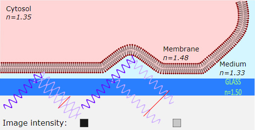
Optical Microscopy: Interference reflection --- from wikipedia---(IRM) is an optical microscopy technique that utilizes polarized light to form an image of an object on a glass surface. The intensity of the signal is a measure of proximity of the object to the glass surface. This technique can be used to study events at the cell membrane without the use of a (fluorescent) label in contrast to TIRF microscopy.
To form an image of the attached cell, light of a specific wavelength is passed through a polarizer. This linear polarized light is reflected by a beam splitter towards the objective, which focuses the light on the specimen. The glass surface is reflective to a certain degree and will reflect the polarized light. Light that is not reflected by the glass will travel into the cell and be reflected by the cell membrane. Three situations can occur. First, when the membrane is close to the glass, the reflected light from the glass is shifted half of a wavelength, so that light reflected from the membrane will have a phase shift compared to the reflected light from the glass phases and therefore cancel each other out (interference). This interference results in a dark pixel in the final image (the left case in the figure). Second, when the membrane is not attached to the glass, the reflection from the membrane has a smaller phase shift compared to the reflected light from the glass, and therefore they will not cancel each other out, resulting in a bright pixel in the image (the right case in the figure). Third, when there is no specimen, only the reflected light from the glass is detected and will appear as bright pixels in the final image.
The reflected light will travel back to the beam splitter and pass through a second polarizer, which eliminates scattered light, before reaching the detector (usually a CCD camera) in order to form the final picture. Note that the polarizers can increase the efficiency by reducing scattered light, however in a modern setup with a sensitive digital camera, they're not required.
Theory
Reflection is caused by a change in the refraction index, so on every boundary a part of the light will be reflected. The amount of reflection is given by the reflection coefficient {\displaystyle r_{12}\!} r_{{12}}\!, according to the following rule:
{\displaystyle r_{12}={\frac {n_{1}-n_{2}}{n_{1}+n_{2}}}} r_{{12}}={\frac {n_{{1}}-n_{{2}}}{n_{{1}}+n_{{2}}}}
Optical Microscopy: Fluorescence Microscopy
--- From wikipedia ---
A specimen is illuminated with light of a specific wavelength (or wavelengths) which is absorbed by the fluorophores, causing them to emit light of longer wavelengths (i.e., of a different color than the absorbed light). The illumination light is separated from the much weaker emitted fluorescence through the use of a spectral emission filter. Typical components of a fluorescence microscope are a light source (xenon arc lamp or mercury-vapor lamp are common;
more advanced forms are
high-power LEDs and lasers), the excitation filter, the dichroic mirror (or dichroic beamsplitter), and the emission filter (see figure below). The filters and the dichroic beamsplitter are chosen to match the spectral excitation and emission characteristics of the fluorophore used to label the specimen.[1] In this manner, the distribution of a single fluorophore (color) is imaged at a time. Multi-color images of several types of fluorophores must be composed by combining several single-color images.[1]
Most fluorescence microscopes in use are epifluorescence microscopes, where excitation of the fluorophore and detection of the fluorescence are done through the same light path (i.e. through the objective). These microscopes are widely used in biology and are the basis for more advanced microscope designs, such as the confocal microscope and the total internal reflection fluorescence microscope (TIRF).
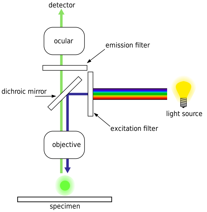
image:
By derivative work: Henry Mühlpfordt (talk)Fluoreszenzmikroskopie_2008-09-28.svg: *derivative work: Henry Mühlpfordt (talk)FluorescenceFilters.svg: Krzysztof Blachnicki - Fluoreszenzmikroskopie_2008-09-28.svg,
CC BY-SA 3.0, Link
Epifluorescence microscopy
The majority of fluorescence microscopes, especially those used in the life sciences, are of the epifluorescence design shown in the diagram. Light of the excitation wavelength illuminates the specimen through the objective lens. The fluorescence emitted by the specimen is focused to the detector by the same objective that is used for the excitation which for greater resolution will need objective lens with higher numerical aperture. Since most of the excitation
light is transmitted through the specimen, only reflected excitatory light reaches the objective together with the emitted light and the epifluorescence method therefore gives a high signal-to-noise ratio. The dichroic beamsplitter acts as a wavelength specific filter, transmitting fluoresced light through to the eyepiece or detector, but reflecting any remaining excitation light back towards the source.
Light sources
Fluorescence microscopy requires intense, near-monochromatic, illumination which some widespread light sources, like halogen lamps cannot provide. Four main types of light source are used, including xenon arc lamps or mercury-vapor lamps with an excitation filter, lasers, supercontinuum sources, and high-power LEDs. Lasers are most widely used for more complex fluorescence microscopy techniques like confocal microscopy and total internal reflection fluorescence
microscopy while xenon lamps, and mercury lamps, and LEDs with a dichroic excitation filter are commonly used for widefield epifluorescence microscopes. By placing two microlens arrays into the illumination path of a widefield epifluorescence microscope, highly uniform illumination with a coefficient of variation of 1-2% can be achieved.
Optical Microscopy: Confocal Microscopy most frequently confocal laser scanning microscopy (CLSM), is an optical imaging technique for increasing optical resolution and contrast of a micrograph by means of using a spatial pinhole to block out-of-focus light in image formation. Capturing multiple two-dimensional images at different depths in a sample enables the reconstruction of three-dimensional structures (a process known as optical sectioning) within an object. This technique is used extensively in the scientific and industrial communities and typical applications are in life sciences, semiconductor inspection and materials science.
Light travels through the sample under a conventional microscope as far into the specimen as it can penetrate, while a confocal microscope only focuses a smaller beam of light at one narrow depth level at a time. The CLSM achieves a controlled and highly limited depth of focus.
The principle of confocal imaging was patented in 1957 by Marvin Minsky and aims to overcome some limitations of traditional wide-field fluorescence microscopes.[3] In a conventional (i.e., wide-field) fluorescence microscope, the entire specimen is flooded evenly in light from a light source. All parts of the specimen in the optical path are excited at the same time and the resulting fluorescence is detected by the microscope's photodetector or camera including a large unfocused background part. In contrast, a confocal microscope uses point illumination (see Point Spread Function) and a pinhole in an optically conjugate plane in front of the detector to eliminate out-of-focus signal – the name "confocal" stems from this configuration. As only light produced by fluorescence very close to the focal plane can be detected, the image's optical resolution, particularly in the sample depth direction, is much better than that of wide-field microscopes. However, as much of the light from sample fluorescence is blocked at the pinhole, this increased resolution is at the cost of decreased signal intensity – so long exposures are often required. To offset this drop in signal after the pinhole, the light intensity is detected by a sensitive detector, usually a photomultiplier tube (PMT) or avalanche photodiode, transforming the light signal into an electrical one that is recorded by a computer.
As only one point in the sample is illuminated at a time, 2D or 3D imaging requires scanning over a regular raster (i.e., a rectangular pattern of parallel scanning lines) in the specimen. The beam is scanned across the sample in the horizontal plane by using one or more (servo controlled) oscillating mirrors. This scanning method usually has a low reaction latency and the scan speed can be varied. Slower scans provide a better signal-to-noise ratio, resulting in better contrast and higher resolution.
The achievable thickness of the focal plane is defined mostly by the wavelength of the used light divided by the numerical aperture of the objective lens, but also by the optical properties of the specimen. The thin optical sectioning possible makes these types of microscopes particularly good at 3D imaging and surface profiling of samples.
Successive slices make up a 'z-stack' which can either be processed by certain software to create a 3D image, or it is merged into a 2D stack (predominately the maximum pixel intensity is taken, other common methods include using the standard deviation or summing the pixels).
Video:Title: Fluorescent and confocal microscopes.webm
Author: Jubobroff. Date: 8 June 2016
Confocal microscopy provides the capacity for direct, noninvasive, serial optical sectioning of intact, thick, living specimens with a minimum of sample preparation as well as a marginal improvement in lateral resolution.[4] Biological samples are often treated with fluorescent dyes to make selected objects visible. However, the actual dye concentration can be low to minimize the disturbance of biological systems: some instruments
can track single fluorescent
molecules. Also, transgenic techniques can create organisms that produce their own fluorescent chimeric molecules (such as a fusion of GFP, green fluorescent protein with the protein of interest). Confocal microscopes work on the principle of point excitation in the specimen (diffraction limited spot) and point detection of the resulting fluorescent signal. A pinhole at the detector provides a physical barrier that blocks out-of-focus fluorescence. Only the in-focus, or central spot of the airy disk, is recorded.
Raster scanning the specimen one point at a time permits thin optical sections to be collected by simply changing the z-focus. The resulting images can be stacked to produce a 3D image of the specimen.
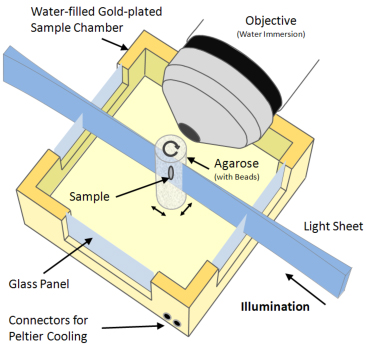
Optical Microscopy: Light sheet fluorescence microscopy (LSFM) is a fluorescence microscopy technique with an intermediate-to-high optical resolution, but good optical sectioning capabilities and high speed. In contrast to epifluorescence microscopy only a thin slice (usually a few hundred nanometers to a few micrometers) of the sample is illuminated perpendicularly to the direction of observation. For illumination, a laser light-sheet is used, i.e. a laser beam which is focused only in one direction (e.g. using a cylindrical lens). A second method uses a circular beam scanned in one direction to create the lightsheet. As only the actually observed section is illuminated, this method reduces the photodamage and stress induced on a living sample. Also the good optical sectioning capability reduces the background signal and thus creates images with higher contrast, comparable to confocal microscopy. Because LSFM scans samples by using a plane of light instead of a point (as in confocal microscopy), it can acquire images at speeds 100 to 1000 times faster than those offered by point-scanning methods.
This method is used in cell biology and for microscopy of intact, often chemically cleared, organs, embryos, and organisms.
Starting in 1994, LSFM was developed as orthogonal plane fluorescence optical sectioning microscopy or tomography (OPFOS) mainly for large samples and later as the selective/single plane illumination microscopy (SPIM) also with sub-cellular resolution. This introduced an illumination scheme into fluorescence microscopy, which has already been used successfully for dark field microscopy under the name ultramicroscopy.
Optical Microscopy: Single Plane Illumination Microscopy
A Single Plane Illumination Microscope (SPIM) is being developed at CABI to record high-resolution, three-dimensional, optical images. Constructed with two lasers, this system will allow illumination at two different wavelengths. The system is being built following the OpenSPIM specification, in collaboration with Pavel Tomancak at the Max Planck Institute of Molecular Cell Biology and Genetics (MPI-CBG), Dresden.
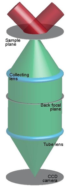
SPIM principle
In SPIM, optical sectioning is achieved by illuminating the sample with a sheet of laser light. The specimen is attached to a stage, rotated and translated orthogonally to the light sheet. Image stacks are acquired along multiple directions and then merged into a single three-dimensional data set. The specimen is illuminated from one side and fluorescent light is collected by a detector positioned perpendicularly to the light sheet. Since each plane is illuminated only once, fluorophores outside the focal plane
are not exposed to light, and photo damage is therefore dramatically reduced.
SPIM applications
SPIM is a very promising imaging technique that allows the registration of single-cell resolution images of various kinds of samples. Indeed, it can not only be used to examine large cleared specimens, but also to study the development of small insects and animals (drosophila, zebra fish) over several days.
Note: this section has been copied from UCL and is abridged. Please visit UCL here for better insight.
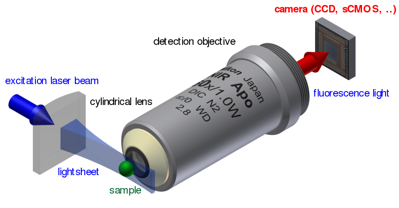
Image by Jan Krieger
wikipedia
Section (text and image) abridged from wikipedia.
Optical Microscopy: Wide-field multiphoton microscopy refers to an optical non-linear imaging technique tailored for ultrafast imaging in which a large area of the object is illuminated and imaged
without the need for scanning. High intensities are required to induce non-linear optical processes such as two-photon fluorescence or second harmonic generation. In scanning multiphoton microscopes the high intensities are achieved by tightly focusing the light, and the image is obtained by stage- or beam-scanning the sample. In wide-field multiphoton microscopy the high intensities are best achieved using an optically amplified pulsed laser source to attain a large field of view (~100 µm).[ The image
in this case is obtained as a single frame with a CCD without the need of scanning, making the technique particularly useful to visualize dynamic processes simultaneously across the object of interest. With wide-field multiphoton microscopy the frame rate can be increased up to a 1000-fold compared to multiphoton scanning microscopy.
Limitations
The limit to which the energy can be increased depends on laser system. Optical amplifiers such as a regenerative amplifier, can typically yield energies of up to mJ with lower repetition rates compared to oscillator based systems (e.g. Ti:sapphire laser).
Possible damage of the optics if the beam is focused somehow somewhere in the optical system to a small area. Different methods exist to achieve the required illumination without risk of damaging the optics (see Methods).
Depth cross-sectioning may be missing.
Advantages
Ultrafast imaging. A single laser shot is needed to produce one image. The frame rate is thus limited to the repetition rate of the laser system or the frame rate of the CCD camera.
Lower damage in cells. In aqueous systems (such as cells), medium to low repetition rates (1 – 200 kHz) allow for thermal diffusion to occur between illuminating pulses so that the damage threshold is higher than with high repetition rates (80 MHz).
The whole object can be observed simultaneously because of the wide-field illumination.
Larger penetration depth in biological imaging compared to one-photon fluorescence due to the longer wavelengths required.
Higher resolution than wide-field one-photon fluorescence microscopy.The optical resolution can be comparable or better than multiphoton scanning microscopes.
This article is by Mol Smith and uses resources from our website www.microscopy-uk.org.uk authored by amateur microscopists who contribute articles to Micscape Magazine.
Some links are used to external resources and copyright lies with those resources. Some material is taken from wilipedia and copied to here.