 |
| A Case for Thin Coverslips Advantages of coverslips of less than 0.17mm thick and their selection for quality imaging at medium to high power in DF & COL By Paul James (uk) |
Most modern medium to high power dry objectives are designed to operate through 0.17mm coverslips, but in practice the total thickness or depth of coverslip/mountant above the specimen is often greater than this. In these conditions there will be noticeable spherical aberration, the extent of which is directly proportional to the thickness of the coverslip/mountant, the value of numerical aperture of the objective and finally the type of illumination in use.
The need to match mountant/coverslip thickness to that of the objective remains as important as ever, and in my humble opinion even more so now as many amateurs now possess higher apertured, more sophisticated optics than ever before. It seems therefore a step backwards to use these high quality optics whilst at the same time ignoring the basic relationship between the coverslip/mountant thickness for a given objective.
Though the ubiquitious x 10 objective is quite insensitive to coverslip thickness, higher na. examples are to some extent observably sensitive, and certainly the x 20 at around 0.4 na. shows definite signs of being so. The standard x 40 dry achromatic objective at around 0.65 na. and those more exotic examples without correction collars at around 0.75 na are very definitely sensitive to variations from the designated 0.17mm.
Keep in mind the distinct possibility that any objective's designated 0.17mm coverslip correction might vary too, and could account for unexpected coverslip thicknesses being required for optimum performance.
The spherical aberration encountered in overly thick preparations is observable in Brightfield, but much more so in Darkfield and COL, where it can spoil the delicate overall imagery that these sophisticated optics were designed to provide.
Measuring coverslip thickness
We tend to accept that a boxful of coverslips are of the same thickness, or at least assume that they are close to the designated 0.17mm. The fact is that unless you measure these coverslips, especially from a batch from an unknown source you cannot really know how close they are to 0.17mm.
Ideally, coverslips which are 0.17mm OR better still less............ say 0.15 - 0.16mm are required to allow for inclusion of mountant and which satisfy the optical requirements of the higher power objectives.
It pays therefore to 'select' coverslips from your box because in all probability they will not be identical in thickness. A figure of 20% variation in thickness is often cited, so expect a range of thicknesses of around 0.15mm up to 0.20mm from a box of " 0.17mm ".
|
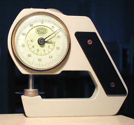
I was lucky to chance upon this 'thumb wheel' micrometer which I use amongst other things to gauge the thickness of coverslips. It is easy to manipulate and read the scale which is marked off in 0.01mm intervals. The above image shows a coverslip which has a thickness of a shade under 0.15mm....... near perfect for aquatic use.
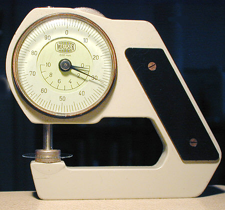 |
This one measured a little over 0.3mm! Of the sample of about 50 coverslips I measured, 3 or 4 were 0.3mm and about 5-6 measured 0.15mm-0.16mm, the rest falling into the thicker than ideal region of about 0.20mm. Very few were 0.17mm.
These results from one batch of coverslips may not be typical BUT the fact is that without measurement you cannot be sure.
OTHER WAYS OF MEASUREMENT
Vernier gauges and standard micrometers can be used too of course, but these are not every day pieces of equipment that the amateur microscopist uses. However, the microscope itself is in fact a very accurate measuring device, especially if the fine focus control on you 'scope is calibrated.
USING THE FINE FOCUS METHOD
To facilitate this, the fine adjustment must have its periphery marked off in 0.001 mm or 0.002 mm divisions. Thus by examination of the top and bottom surfaces of a coverslip with say a x 10 objective we can assess its thickness as accurately as by mechanical means. If your microscope's fine focus is marked off in imperial divisions of 0.001" etc........ then 0.17mm is around 0.006".
Take the uncleaned coverslip and place on a clean slide then note the markings on the fine focus control both when the objective is focussed on top and then bottom of the coverslip surface. This takes a little practice and it is vital that you are aware of the direction of rotation of the fine focus and how it relates to the top and bottom focus position. Of course there should be dust particles on each surface of the coverslip to render focussing easier. Going through the process several times is necessary before we can place any confidence in our methodology. It soon becomes a simple matter once you have got the basics sorted out and I find Dark Field illumination helps too with focussing accuracy.
Each division on the fine focus is usually 0.001 mm so a coverslip will normally require about 1.2* revolutions to raise the 'scope from lower surface to the upper. Since there are usually 100 divisions on the fine focus control ring it can be confusing when trying to "add up" the total number of divisions as the "0" will have been passed once. Practice makes perfect, and before long accurate readings will ensue.
Translating the readings
The figure you arrive at, after measuring a couple of times to make sure it is accurate, is the "apparent"* depth or thickness of the coverslip. Thus this figure is not the actual physical depth of the coverslip but one modified by the refractive index of the glass itself.
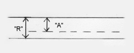 |
The figure you have for the thickness is actually the one marked "A" above and is known as the apparent thickness. The real thickness "R" is easily calculated by simply multiplying the "A" x the refractive index of the coverslip. Thus :-
"A" x 1.52 = "R"
So if your measurement of the apparent thickness of the coverslip is 116 divisions, this equates to 0.116 mm of apparent thickness, and needs amplifying by the refractive index to yield the real thickness:-
0.116 x 1.52 = 0.17632 mm
If the measuring is done carefully, and also allowing for very slight refractive variations of the glass, then the figure above could confidently be taken as between 0.173 to 0.178 mm. This is certainly accurate for our purposes !
Is all this a little trivial and of little use in practical microscopy?
If you have got this far you may be wondering about the sense of it all. The simple fact is that coverslip thickness is important in quality microscope imaging using objectives of moderate to higher powers. The Victorian microscopists and microscope manufacturers were very aware of all this because they were the pioneers in that era. Their observations of image quality concerning the correlation of coverslip/mountant thicknesses with the higher powers resulted in coverslips being offered in at least 3 thickness ranges.
Those who are keen practitioners of aquatic life studies might benefit from using thinner coverslips :-
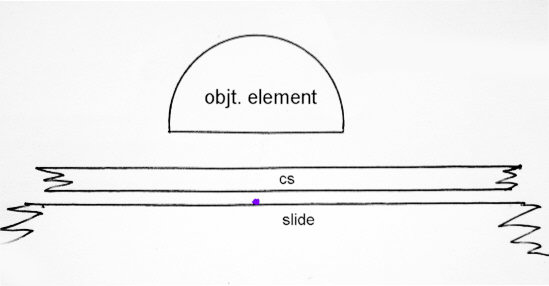 |
The image above roughly shows the problem in that there will always be a water/fluid/mountant gap just above the specimen, which if a protozoan, will invariably be on the slide's surface leaving perhaps 20-100 microns 0.020-0.100mm) gap above.Thus a standard 0.17mm coverslip in this situation would bring about a total of about 0.19-0.27mm c'slip/mountant thickness. In average pond life observations this 'gap' can be several times this figure, resulting in even more imperfect imaging from a high quality objective.
Keeping bulky mucilage and debris off the slide is of paramount importance, and supports the principles of using apparatus such as that described in Walter Dioni's March 2005 article for extracting just the specimens with as little unwanted material as possible.
Conclusion
Anyone possessing high quality optics in the form of either Achromats, Fluorites or Apochromats in the x20-x40 region without correction collars, and who have not attended to the finaries of coverslip/mountant constraints are not getting the best images from them. The prudent photographer would never record images using a first class optic in his camera on an old outdated coarse grained film for rather obvious reasons. And so it follows that the ownership of one of the finest optics from the likes of Zeiss, Leitz, Wild, and others, inevitably requires that it is used in as ideal conditions as possible to elicit the finest imagery that its pedigree deserves.
Ensuring that the coverslip is flat, clean and of the correct depth or thickness when taking into account the mountant too, gives the objective its opportunity to provide us with its very best imagery.
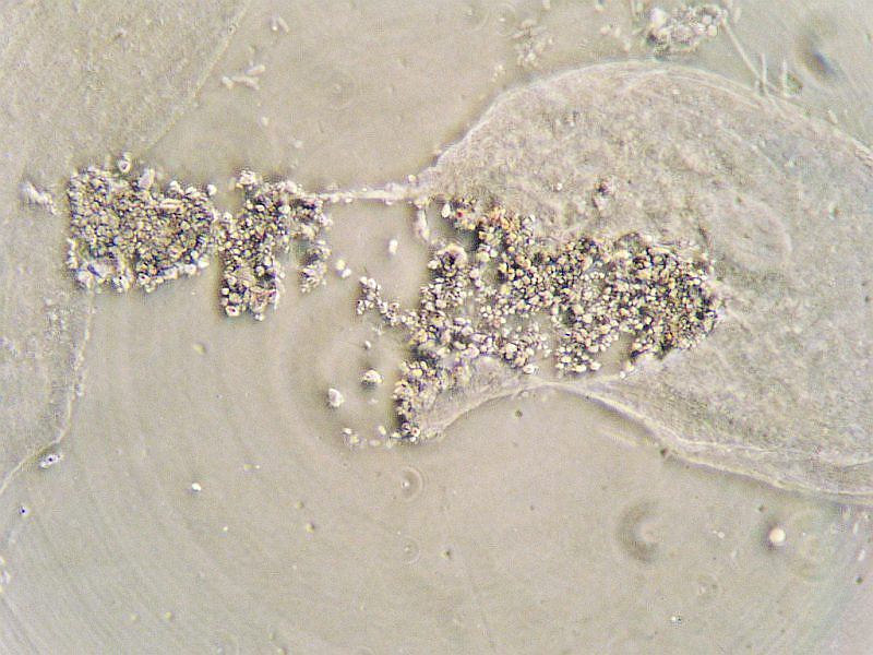 |
'Ruptured epithelial cheek cell' x2900, Wild x40 Fluotar 0.75na COL from max aperture annulus. A coverslip of 0.14mm was used here which suited this objective perfectly. This image which has been amplified optically onto the CCD of the camera is well beyond the '1000 x na' figure accepted for maximum photographic magnification from a given objective. Concentric rings are artefacts from camera lens with COL. |
Bottom Line
The coverslip IS the first effective optical element of the objective, and if it is not as it should be then the rest of the optical train cannot correct the resulting aberrations, which applies especially to the x20 objectives upwards.
| All comments welcome by the author Paul James |
Microscopy
UK Front Page
Micscape
Magazine
Article
Library
Please report any Web problems or offer general comments to the Micscape Editor.
Micscape is the on-line monthly magazine of the Microscopy
UK web
site at Microscopy-UK
© Onview.net Ltd, Microscopy-UK, and all contributors 1995 onwards. All rights reserved. Main site is at www.microscopy-uk.org.uk with full mirror at www.microscopy-uk.net .