Victorian microscopy ca. 1860 - a hands-on comparison of microscopy techniques then and now.

Part 1 - Qualitative polarised light microscopy.

by David Walker, UK


Image left: A Ross No.2 bar limb design microscope ca. 1860 set up for polarised light studies.
A- Nicol prism analyser above objective, R - 3 swing in retarders, P - Nicol prism polariser.

Series introduction. One of the appeals of antique microscopes is that they allow a user to explore the implementation of techniques at the time of manufacture, aided by textbooks of the time and to compare them with modern microscopy practice. Using a well specified Ross No.2 microscope ca. 1860 as an example, the various techniques it offered are compared with the same methods as used on a typical research microscope of the second half of the 20th century, a Zeiss Photomicroscope III.

The study of the effect of polarised light on a wide variety of subjects was very popular from the outset of the wide availability of affordable achromatic microscopes. Richard Beck's book 'Achromatic Microscopes' 1865 discusses and illustrates the various methods and accessories available (Plate XVI illustrates typical examples). Copies are available on www.archive.org. The various editions of the classic textbooks e.g. by Hogg and Carpenter also had sections on the technique.

The popularity of these studies was reflected in the wide array of prepared slide subjects—animal, vegetable and mineral—sold by mounters in the 19th century. Subjects particularly suited were labelled variously as 'Polar' or 'For Polariscope'. The practice has continued with some mounters until recently and a selection of these slides are shown right. The red papered slides are by the famous maker Edmund Wheeler.

Studies of these subjects by the amateur were primarily qualitative e.g. to enjoy the often striking imagery although the technique could enhance the visibility of some objects or their features.

In the second half of the 19th century, even the most basic microscope e.g. those without a substage or condenser were often supplied with a polariser and analyser. More sophisticated stands such as the Ross described here had a wider range of accessories and polarisers of higher quality. (This is in contrast to today it seems, where basic polarising facilities aren't typically included even with quite advanced models, despite the cheapness of modern polarisers.)

Quantitative polarisation microscopy and the associated development of the petrographic microscope was still in its relative infancy at the time of the Ross microscope used as an example here (see the Timeline in Kile's book below).

A superb illustrated bookl discussing the development of quantitative methods is 'The Petrographic Microscope: Evolution of a Mineralogical Research Instrument'' by Daniel E Kile 2003. Special Publication No. 1 published by 'The Mineralogical Record'.

Detail of the Ross No.2 bar limb design microscope ca. 1860 set up for polarised light studies.

A- Nicol prism analyser above objective, R - 3 swing in retarders, P - Nicol prism polariser.

The substage condenser mount is fully rotatable via the rack and pinion and also centrable. A lock on the rotation would have been useful as the setting easily shifts when using the retarders.

The polariser P fully rotates in its mount so that it can be set to the orientation required with respect to the retarders and analyser. (This microscope and procedures predates the now typical E-W orientation of setting polarisers.)

The slide stage plate is fully rotatable, but it acts above the x - y controls, so it is not possible to set the stage rotation to be permanently concentric with the objective optical axis. Thus a feature isolated on the slide will swing in an arc out of the field of view if wish to rotate it between the crossed polars.

Victorian polarisers and analysers - Nicol prisms.

One of the commonest form of polarisers in the 19th century were Nicol prisms invented by William Nicol in 1829 who also developed the thin section preparation invaluable for later quantitative polarising studies. The polariser and analyser using these prisms are shown right, the former fitting in the substage mount where present as in the Ross. As shown, the polarisation axis is N-S established by crossing with a modern polariser.

Two forms of Nicol prism analyser were common. The example shown far right fitted immediately above the objective and screwed into the lower end of the eyepiece tube. The cited advantage of this method was that a full field of view was retained at the eyepiece, the disadvantage being that it had to be of high quality to minimise image degradation.

On cheaper stands the quality and size of the prisms was variable. The examples shown are of high quality, the polariser also being larger than many.

Eyepiece polarising accessories.

An alternative to the Nicol prism above the objective was a slip-on prism for an eyepiece. This is shown top right. Its benefit was cited as offering a brighter image than the objective design but at the penalty of a narrower field. When this was set for crossed polars, the two lozenges of clear prism were at right angles and only a quite small area was offered to the viewer.

Another alternative to a Nicol prism as an analyser was a small plate of tourmaline fitting over an eyepiece, an example is shown middle right. This offered a wider field at the eyepiece, but as the transmitted light image right shows, it gave a colour cast to the image.

Double prism eyepiece accessory with subject plate:

The eyepiece attachment shown middle left is an uncut rhombohedron of calcite (in contrast to the Nicol prism) which gave a double image from the ordinary and extraordinary ray (a hole in punched card is sat below it to show this). This was used in conjunction with a perforated plate as a stage subject and retarders if desired to demonstrate the effects of polarised light.

Victorian retarders

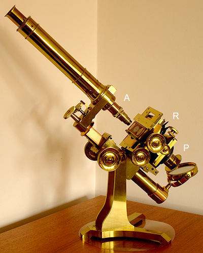
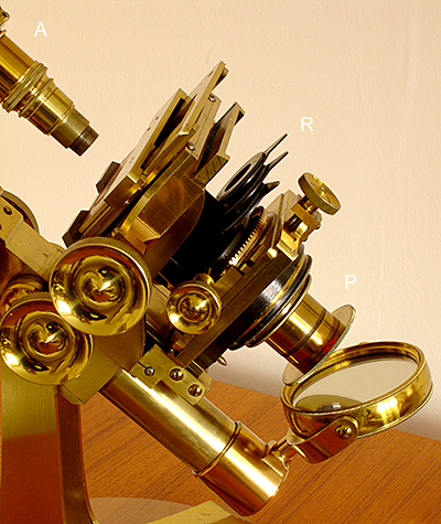
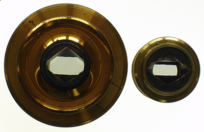
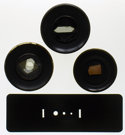
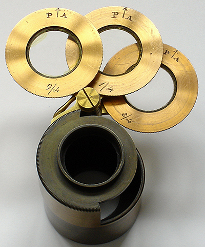
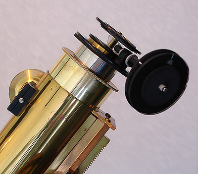
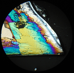
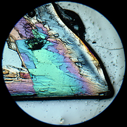
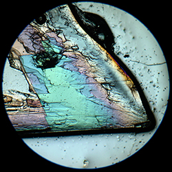
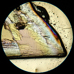
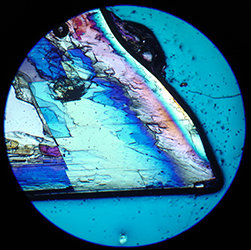
Shown right are the variable retarders enclosed with the Ross, other makers offered similar. They were often called 'Darker's selenites' after William H Darker, a London instrument maker, who was noted for his ability to prepare the thin plates and for his polarisation apparatus. Selenite is a form of gypsum
(hydrated calcium sulphate). The retarders fitted above the polariser on the condenser. Three retarders were offered - 1/4λ , 3/4λ and 9/4λ, PA was the 'positive axis' and each retarder could rotate 360°.

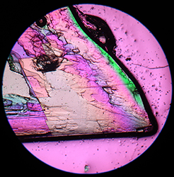
This, at first sight, odd combination of retarders was in reality rather clever. As Beck describes ('Achromatic Microscopes', 1865) it offered 13 retardation settings in ¼λ increments from ¼ to 3¼ wavelengths. These could be achieved by swinging in one or more retarders with their positive axes aligned or one turned 90° to subtract that wavelength from the total. Beck has a table listing all the combinations and their respective primary 
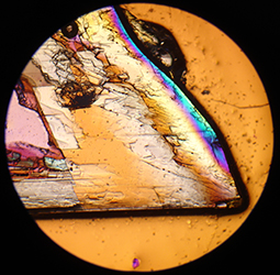
and 'complementary tint'.

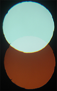
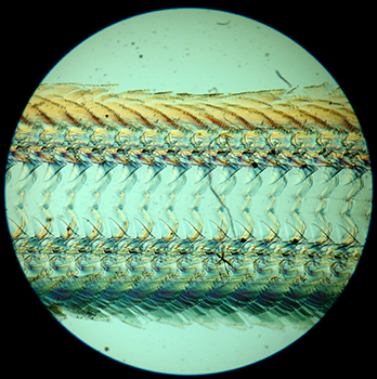
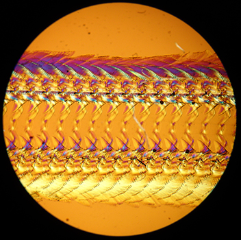
To match the colours Beck describes in his table, a retarder's PA was set parallel to one polariser with the other polariser at right angles, i.e. crossed polars. The 'complementary tint' was achieved by rotating one polariser 90° i.e. uncrossed. This contrasts with the modern practice of keeping the polarisers crossed and inserting the retarder at a fixed 45° angle to both polarising axes.

In use. Although offering a wealth of retardation settings, I found it a rather awkward device to use. It is nestled below the busy stage and does not offer a good view of, or easy access to, the retarders to make changes or check what has been set. I put white marks on the side of each so could check the orientation from the side. The freely rotating condenser mount could also easily be rotated out of alignment while adjusting retarder settings.

With the set of selenites in place, the polariser is some distance from the stage and can affect the aperture. A condenser can be used above the retarders for higher powers as advised by Beck.

Other methods of introducing retarders included a brass plate that sat below the slide on the stage, with either exchangeable retarders or rotatable to give variable retardation.

Examples of variable compensators built by enthusiasts. See the next section below for modern fixed retarder approaches. Commercial variable retarders are a typically expensive special accessory for modular research scopes and advanced polarising microscopes for quantitative rather than qualitative studies. It can take the form of e.g. a quartz wedge that sits above the objective or various calibrated designs of variable retarder e.g. for the eyepiece.

Some enthusiasts have made their own variable compensator.

Ian Walker made a tilting Berek style compensator just using stiff card and a cleaved piece of mica to sit below the stage on the lamp field lens, shown right. This design relies on continuously varying the thickness of angled mica, in contrast to inserting one or more sheets of mica or other material corresponding to a known retardation value as used above by Ross. Image courtesy of Ian Walker.

Ian later developed this into a miniature version to sit above the eyepiece of an older microscope without a built in lamp. Shown lower right. Image courtesy of Ian Walker.

Jay Phillips designed and made an elegant calibrated 'variable rotation filter' akin to the Victorian method of using a selenite stage. Shown below. Image below courtesy of Jay Phillips.

Typical modern polarisers and analysers, post introduction of Polaroid as used in the Zeiss Photomicroscope series.

Bottom left: A simple high quality glass Zeiss analyser that can either sit in the condenser filter tray or on the field lens base. A white line indicates the polarising axis, typically set E-W.
Top middle: A basic analyser using the Zeiss filter tray and fits in a slot above the objective nosepiece.
Top left: The more sophisticated Zeiss analyser using the same filter slot allows full rotation with accurate micrometer setting of the polarising axis. Somewhat overkill for qualitative work but a delight to use.
Top right: The retarder filter tray (empty here) sits at 45º to and below the analyser slot. Common retarders are the quarter and full wave plate.
Like many users, I prefer not to use a retarder above the objectives—it's one extra optically demanding element—sitting the retarder on the analyser, below the stage allows cheaper grade filters to be used for qualitative studies. They can be set by eye to 45º to the polariser axis.

Double prism eyepiece accessory in use. Ross 2 inch objective.

The metal perforated slide shown above was used with a polariser on the substage but no analyser. By rotating the eyepiece with double prism attached, the tints for the ordinary and extraordinary rays are shown, in this case for 1λ (¾ + ¼) retarders in place. The colours shift as rotate by 90°.

The larger hole in the slide gives overlapping images as shown, for the smaller hole they do not overlap.

This is a simple but effective way of demonstrating the double refraction of a calcite prism and the associated polarised and unpolarised rays it creates.

There's no reason why this accessory could not be used nowadays to help demonstrate the principles associated with polarised light.


Victorian papered slide 'Palate of Haliotis' i.e. the radula or teeth of the abalone mollusc. 1½ inch objective.
Parallel polars plus λ retarder.


As left but crossed polars plus λ retarder.

Image right: Biosil slide of musk ketone crystals.
Objective 2/3 inch with
retarders between crossed polars.

Full field after field stop edge cropped.

Final comments. It was very enjoyable as well as instructive learning how the Victorians practiced polarised light microscopy. For qualitative studies, there's little the Ross couldn't do using the technique that couldn't match a modern research microscope. The lower power objectives were well corrected and near flat to the edge. The Ross 'A' eyepiece field number was comparable to modern examples for a good field of view and the optics overall offered little loss of image quality cf modern objectives.

Compared with a modern microscope I would say that the weaker aspects of the Ross design, was the rotating stage above the x-y controls thus losing the optical axis if scanned slide. Also the selenite plates in use, although versatile, were rather fiddly.

Comments to the author David Walker are welcomed.

    Microscopy UK Front Page
    Micscape Magazine
    Article Library


    © Microscopy UK or their contributors.

    Published in the April 2015 edition of Micscape.

    Minor revisions May 14th 2015

    Please report any Web problems or offer general comments to the Micscape Editor .

    Micscape is the on-line monthly magazine of the Microscopy UK web site at Microscopy-UK


    © Onview.net Ltd, Microscopy-UK, and all contributors 1995 onwards. All rights reserved.
    Main site is at
    www.microscopy-uk.org.uk with full mirror at www.microscopy-uk.net .