Topical tip: Practical notes on using off-axis
oblique
illumination
by David Walker, UK
Off-axis (anaxial) oblique is a popular contrast enhancement technique for the
microscopy enthusiast as it can be both very effective and readily tried
on most compound microscopes at little cost. Resources by Micscape contributors
on both the off-axis and annular oblique technique are in the Micscape Library
- Oblique.
The textbooks often advise that care needs to be taken with off-axis
oblique with
the user making critical assessments of the image and also comparing the results
with other techniques to ensure what is seen is genuine. This is with good
reason as the technique for certain subjects may create artifacts or
structures that are misleading or false.
It is
worth ensuring that for the off-axis oblique method used, both the extent and
orientation of the oblique can be controlled to study subjects under varying
conditions. Some methods for controlling
these parameters are summarised
below, with notes on ensuring reproducibility, followed by examples of false and real structures that can be seen.
Note
that only off-axis oblique is being discussed. Annular oblique (also called circular oblique (COL)) is primarily
a uniform oblique illumination. See Micscape Library link above for contributors'
articles on COL.
The underlying theory
for why oblique can offer both contrast enhancement and increased resolution
cf brightfield is superbly described and illustrated in Molecular Expressions
'Introduction
to oblique illumination'.
|
Off-axis oblique method
|
Controlling extent and orientation
|
Angling the mirror
or external light source off the optical axis (for microscopes with external lighting).
For
microscopes with built in lamp, off-setting the lamp filament has
been suggested. The practicality may depend on how easy it is to
recentre the lamp. For the author's Zeiss stand, where centring
the 100W halogen lamp filament and its mirror image takes time and
care, I don't find this very practical.
|
This
a more basic method with the least reproducible control, the methods below
are arguably better.
|
Inserting stops with variously shaped cut-outs into the
condenser filter tray.
These can be readily be made out of opaque card although
some older scopes came supplied with a set of stops, which
typically included rectangular, triangular and crescent shaped cut-outs.
Variants of filter stops include for example the Mathias arrow (see
Walter Dioni's article).
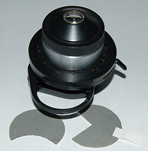
A
typical Abbe condenser (a LOMO) with swing out filter tray with
two examples of homemade stops. A paper tab can be added as
shown on righthand stop.
|
Extent:
the size and shape of the cut-out but the swing-in filter tray may
also offer some control, also experiment with condenser iris between
open and stopped down somewhat.
Orientation:
the stop can be rotated in the filter tray mount by hand; a
better method is to attach a small paper tab on the stop to allow
it to be rotated. Alternatively if a rotating stage is used, the
specimen can be rotated with respect to the stop.
|
On a phase condenser,
moving the brightfield port, darkfield / phase ring off-axis.
Zeiss
phase condenser, view of back focal plane of a 25x NA0.45 objective.
L to
R, just off-centre brightfield port, darkfield and phase '2' plate.
For
brightfield, the aperture iris partly controls effect, experiment
with iris setting as also controls NA.
Even slight oblique as shown for brightfield
port, can often improve contrast considerably e.g. for diatoms.
For
the Zeiss condenser the orientation is fixed, see right.
|
Extent:
moving partially off-axis the large crescent of the brightfield
port and controlling aperture iris setting. Or the
phase rings of various sizes offer a variety of oblique shapes to
try off-axis.
Orientation:
depending on the phase condenser design the orientation may be fixed.
In which case it is important that the specimen can be rotated
with respect to the condenser.
This
is the author's
preferred method on a Zeiss stand using the phase condenser and
rotating stage.
|
Using a dedicated oblique condenser, e.g.
the LOMO aplanatic oblique condenser, or the condenser often fitted as standard
in earlier models by e.g.
Zeiss or Leitz.
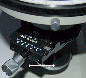
The
LOMO aplanatic oblique condenser. The knob controls the aperture
offset and is graduated in mm either side of centre; the whole
unit can be rotated as shown by arrows to change orientation of
oblique with respect to specimen.
|
Extent:
The condenser iris was usually moved off-axis on a graduated
slider and also offered rotation.
Orientation: the condenser
iris could be rotated round the optical axis.
|
Reproducibility
Unlike
an enhancement technique like phase, where for a given objective the phase plate
is aligned exactly, for the same objective many variations of the type (e.g.
stop shape), extent and orientation of the oblique are possible. This is an
advantage for creating the enhancement desired but also a potential disadvantage
if trying to reproduce an exact setup at a later date or recording what
was used to take a photomicrograph.
Like many enthusiasts
no doubt, I have printed blank forms for recording all the usual microscope
and camera parameters when taking a photomicrograph. More recently I've extended
it to record all the parameters of oblique used, particularly when studying
some critical diatoms where the difference between oblique settings for resolution
of punctae or not can be quite critical. The example below is for a phase
condenser, the parameters would of course differ if say a dedicated oblique
condenser was used.
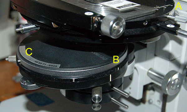
The Zeiss brightfield
/ phase / darkfield condenser which the author uses for off-axis oblique on
a Zeiss stand. To quantify, and later reproduce if needed the oblique setting
used, the following are measured.
A - the angle of the stage to record the
orientation of the oblique to the subject (on the author's example a homemade
graduated scale). If studying a diatom strew slide at higher powers, the x /
y controls of stage are also noted to record which diatom was studied.
B
- the brightfield / darkfield / phase ring used, and which direction it was
offset. The extent of oblique, in this case the distance of the '3' phase
ring from white bar 'click stop' for normal use, is measured with a thin
strip of 1 mm gridded graph paper.
C - if using an off-centre brightfield
position, the iris aperture forms one edge of the oblique cut-out and affects
NA used; the iris setting can be read off the graduated scale.
Note
added Dec. 15th 2008. H. Wessenberg and H. K. Reed in their paper "The
use of oblique illumination in microscopic observations of living protozoa",
Transactions of the American Microscopical Society, 1971, Vol. 90, No.
4, pp. 449-457, describe another way of using the Zeiss phase condenser for
creating oblique by 'decentering' the 'first accessory lens' or lower
swing out 'accessory lens'. Their images of protozoa are most impressive.
With thanks to A. Selwyn St. Leger for pointing out this reference.
Examples
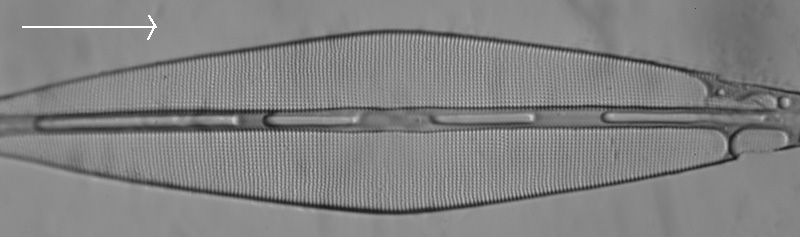
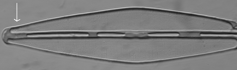
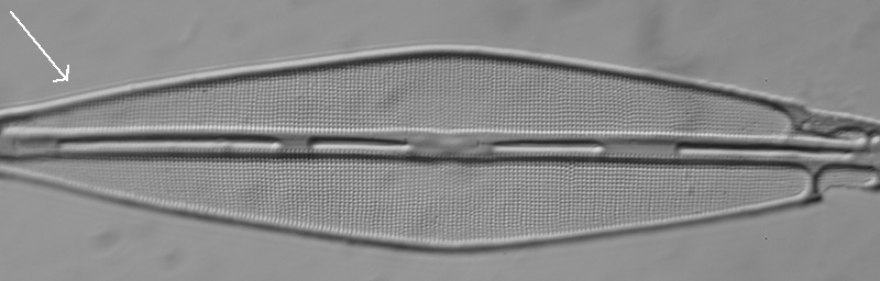
Diatom
Frustulia rhomboides
This diatom frustule
is a
good subject for demonstrating the effect of oblique orientation on structure
(as interpreted by the optical microscope).
Zeiss 100X NA1.3
objective, blue-violet filter, Nikon D300 DSLR in monochrome.
Oblique ca.
30% of full aperture with offset brightfield port in phase condenser.
Images
out of camera. Klaus Kemp '8 form test plate'.
Arrows show direction of off-axis
oblique.
Above: With the
oblique orientated along the diatom long axis, little evidence is seen of
the peripheral structure of the frustule. In this lighting the shadowing
suggests there are raised features along the central long axis.
Punctae resolution is partial
but taking on the appearance of false vertical striae. The striae are often
more noticeable when the objective NA is only just sufficient to resolve
the punctae. In this case it is well within the capabilities of the objective.
Above: With the
oblique orientated vertical to the diatom long axis, the peripheral
structure is shown. The shadowing now makes the features along the long
axis look recessed.
The punctae resolution
is better but near the diatom axis they are taking on the appearance of false horizontal striae.
Above: With the
oblique orientated approximately 45° to the diatom long axis,
the peripheral structure is shown and the
punctae resolution is optimised without showing any false striae.
It can be difficult
deciding from the optical microscope's interpretation of the frustule detail what
the real structure is. SEM imagery also shows that the internal and external
detail of the frustule can be very different for a given diatom species.
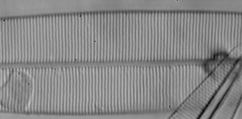
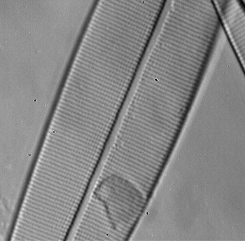
Diatom Amphipleura
pellucida
A classic test diatom,
with punctae spacing ca. 0.25 µm, i.e. at or near the limit of the visible light
microscope, and thus a popular challenge amongst microscopy enthusiasts since
the 19th century. One of the best descriptions
of using oblique for resolving punctae on this diatom is in Edmund Spitta's 'Microscopy',
eg 2nd edition 1909. He discusses and illustrates in great detail how to use oblique to affect critical resolution
in A. pellucida as well as explaining the underlying theory. His superb photomicrographs of resolved A. pellucida
punctae and his other striking diatom images I still aspire to reproduce.
Zeiss 100X NA1.3
Neofluar objective, 405 nm interference filter (20 nm half bandwidth) on 100W halogen lamp. (Filter
$5 on eBay. See footnote on source.)
Camera - Opticstar
PL-130M 1.3 Mpixel USB monochrome.
Oblique crescent ca.
25% of full aperture with offset brightfield port in phase condenser.
Victorian
unnamed strew of A. pellucida. Richmond Park, Sirax mount.
In all three
images below, the same diatom specimen was used.
The oblique
orientation was the same, from the left and almost horizontal.
The sequence
is essentially a repeat of the studies that Spitta recommends in the
above reference and shows the effect of rotating the stage to change
the presentation of the specimen to the oblique. (Spitta changed
orientation of the oblique rather than stage as shown here.)
Single VGA images
captured, out of camera except tonal balance improved and normalised
between the three.
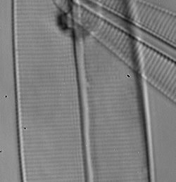
Left: with diatom
perpendicular to oblique, the frustule edges and central axis are shown clearly
but
contrast and detail of the punctae is poor.
Middle: with diatom
long axis parallel to oblique, the frustule detail is seen as parallel lines
or 'striae'. These are false structures of unresolved rows of punctae but
is the accepted appearance of how the visible light microscope interprets the
frustule detail for this alignment of oblique.
Right: with diatom
long axis approximately at 45° to the oblique, the striae take on a beaded appearance
as evidence of individual punctae. In places there's evidence
of full resolution. Spitta notes that this angle is about ideal for punctae
resolution.
The author's example isn't a very good one but gives a feel
for the importance of oblique orientation. Assuming the optics are capable,
achieving the most convincing full resolution can take patience with
careful manipulation of the microscope.
To
see what A. pellucida really looks like, rather than the visible light
microscope's interpretation of it; Gary Gaugler published a fascinating illustrated
paper in
the May 2007 issue of Microscopy
Today, An
SEM analysis of Amphipleura pellucida with
new findings. Also
available as a downloadable
pdf from the Microscopy-UK website, hosted
with the kind permission of Gary Gaugler
and Microscopy Today Editor, Ron
Anderson.
The A.
pellucida
example illustrates the benefit of rigorous recording of the oblique
setup (using the author's Zeiss stand with phase condenser as an example). It's probably not critical for many subjects, but for fellow
enthusiasts
who enjoy the fun (and frustration!) of studying subjects such as Amphipleura
pellucida, the slightest change of
setup can be critical for optimal resolution. I have a single frame on
a roll of monochrome film of my best image to date of A.
pellucida punctae crisply resolved with
a Zeiss 100/1.3 Neofluar with
oblique using modest optics in blue light. Unfortunately I risked using out
of date film developer and a very thin negative resulted. I've yet to recreate
a comparable image as I didn't record exactly how I'd setup the oblique
or which diatom on a strew was imaged.
Comments to
the
author David
Walker
are welcomed.
Footnote:
Interference filters are readily available and good value from some eBay suppliers,
with thanks to Hugo Johnson for telling the author of this source prompted by my
Interference filter article.
©
Microscopy UK or their contributors.
Published
in the December 2008 edition of Micscape.
Please
report any Web problems or offer general comments to
the
Micscape
Editor
.
Micscape
is the on-line monthly magazine of the Microscopy UK web
site at
Microscopy-UK
©
Onview.net Ltd, Microscopy-UK, and all contributors 1995
onwards. All rights reserved.
Main site is at
www.microscopy-uk.org.uk
with full mirror
at
www.microscopy-uk.net
.