 |
| Update on "Foray's into photomicrography with digicams". |
Some further thoughts from the November '99 article by Paul James, (UK)
| Making an accurate base/microscope coupling |
|
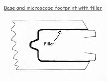
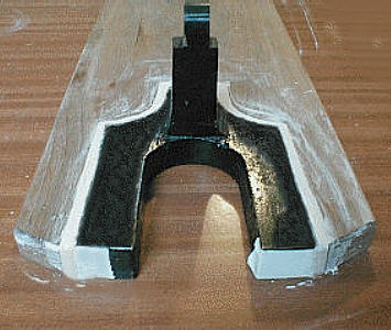
The diagram above shows a way of making an accurate fit for the microscope's footprint from an idea kindly e-mailed to me by Ed Oleen. Basically the method is to cut the footprint about 1/8-1/4" larger all round, so as to leave a gap between the microscope and plywood base. A substance such as plastic wood, or car body filler etc., can then be forced in the gap to take up the space there and automatically provide a perfect fit.
Attention to details is important for success. The microscope's feet must either be parallel, or tapering rearwards, for rather obvious reasons. So you will have to satisfy yourself about this by measuring accurately the foot of your microscope, and that the base will, when the filler is 'cast', slide from the microscope's foot easily and smoothly. If you are not sure about the success of this with your microscope, try a simple and effective method of marking out the microscope's foorprint on cardboard, then cutting accurately and try slipping it in and out to see if it is practical.
Having found that the proposed base will slide in, the next step is to cut the aperture in the plywood base about 1/4" wider all round than the microscope's footprint, leaving the saw marks, but removing dust etc.. I dimpled the face of the wood to be covered with filler, using a bradawl so providing a mechanical 'key' to aid bonding.
Before filling the gap, the foot of the microscope should be protected with some tape, (PVC, parcel, and 'Sello' tapes provide diminishing clearances respectively) being quite suitable, and importantly, will, when removed after filler has hardened , provide a tolerance to allow the base to slide in comfortably, yet accurately.
* Satisfy yourself that the filler you propose to use does not chemically affect the tape, by experimentation.
FILLING
The filler can be almost any proprietary type that hardens and bonds to the wood without significant shrinkage during hardening. "Plastic Wood" and car body fillers are suitable. I tried first with 'Polyfilla' to see if the idea was suitable, and to find out what thickness of tape would yield a nice sliding fit with minimum clearance. PVC tape leaves perhaps just a wee bit too much clearance, but in use the registration between the microscope base and the camera support base was well within the tolerances required.
The filling should be done on a flat smooth surface such as Melamine, Formica etc. The filler should be 'trowelled' in firmly with an even portion all round. It pays to do the filling carefully, but thoroughly as a second attempt is unlikely after hardening! Any 'air' pockets left after hardening may look untidy, but they will be hidden and won't affect the accuracy of the fit.
When hardened thoroughly, the base should be eased away carefully, and the tape peeled away, and all the necessary scraping, filing, sanding and tidying can then be performed. The result produces a nice sliding fit between the camera support base and microscope. If necessary the support can then be adjusted anew to align the camera up to the eyepiece as before.
 |
 |
Above...."Before and After". I have used an offcut of dimensionally stable American walnut for the base above, but I would recommend a piece of quality ply such as marine grade, or perhaps some composition board? There is simply no point in using readily available softwoods as they do not provide the dimensional stability that this technique requires.
| An alternative photomicrographic aid |
For those who have 'difficult' microscope footprints, the following works well, and might suit you. It is certainly the easiest to make, and providing the initial hand alignment skills have been acquired, is the simplest method of taking the occasional photomicrograph
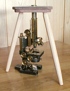
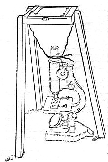
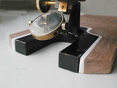
This alternative mounting device which is, as you can see below, a flat topped support on three legs and is extremely sturdy. It is used with my vertical microscope, but not as a holding device as such but rather a double handed support for the digicam. An illustration from Conrad Beck's "The Microscope" gave me the idea.
It's purpose is to have the top flush with the eyepiece, or lower to suit, and so enable a camera to be supported and held simultaneously by both hands, combining the speed and freedom of a handheld camera with the tripod rest as a foundation to 'tweak' the camera's position carefully. The hole for the eyepiece should allow at least 20-30mm of air space all round, to allow easy setting up and removal.
Some of the advantages of this little 'stool' support are that it can be rotated to have it's feet in any suitable position, can be set up and put away in seconds and is very easy to make. Mine was made out of two pieces of scrap ply for rigidity, and three simple wood turned legs. A flimsy stand is worse than useless.
Simple stool which can be rotated to suit lighting source, and provides
very firm support for hands and fingers.
(Note third leg has disappeared!?.)
Illustration in Conrad Beck's book "The Microscope" gave me the idea
of a tripod support. It is a simple way
of using large format photography too.
Height
If you have a microscope which has parfocal objectives your stand needs to be high enough to allow the top of the eyepiece to be in a position just below your camera's lens when held comfortably with fingers resting on the 'stool'. For me this meant the eyepiece being proud of the stand's upper surface by about 5mm, but my objectives are not parfocal, so the easiest course of action was to make the stand some 20-25mm taller and use the eyepiece tube extension to compensate for focusing variations. Cameras with zoom lenses need a taller stand to allow the lens' extension to comfortably protrude below the aperture, and yet allow the hands/fingers to control alignment without damaging the optics.
Tips on Hand Alignment
Assuming that the illumination has been properly set up, it would be wise to centre a simple self contained subject accurately in the field to provide an reference in case your camera's LCD does not show the field edge(s).
There are three fundamental movements necessary to align the camera. Since this has been the common problem with some readers, I'll go through the procedure in order of accomplishment.
It is important to be aware of the three basic steps for successful alignment
Assuming this is the first attempt at aligning the digicam to the eyepiece:-
With the camera held in a way that suits you and yet allows some movement over the eyepiece, locate the circular field edges in the LCD, by bringing the camera a little way from the eyepiece, and look for the small circular image, then carefully move the camera nearer until the LCD is more or less filled with the image circle.
Then 'rock' the camera sideways and/or vertically to centre the field. Notice that purely lateral movement does not substantially alter the position of the field on the LCD, but effects the uniformity of illumination. Concentrate on field centering in the first instance, by getting the image circle/subject matter more or less central on the LCD screen.
When you have experienced this 'field centering' by rocking, move the camera slightly towards and away from the eyepiece and notice that the proportion of illuminated field gets smaller as the camera gets nearer, and also when further away from the eyepiece. In between these extremes will be found the correct position with a fully illuminated field, and when in this position slight lateral movement might be needed to optimize the field. Any further problems experienced with uneven illumination will almost certainly be caused by too intense illumination, or insufficient width of illumination from the condenser, and also improper adjustments of substage lighting generally.
To master all three movements takes a little time, but once mastered it can be done almost simultaneously in seconds, without conscious thought. I stress the fact that it is important to understand the effects of the three basic movements, and bring some 'methodology' into aligning the camera. If still having problems, err on the upper side of the 'ideal' eyepiece/camera distance, use a modest iris opening in substage, and modest lighting output, as this is more likely to yield more even illumination in the initial stages.
Very Important: As I have a fixed focal length lens which is housed within the body of the camera, contact between this lens and the eyepiece is impossible. Those with zoom lenses or projecting fixed focal length varieties must be aware of the possible damage incurred if care and forethought is lacking.
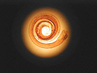
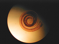
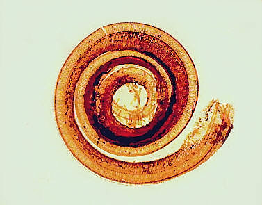
The images below are shown as examples of what you might encounter, though the size of the field will vary from camera to camera
(The subject is a Moth's tongue magnified 100 times in brightfield through aging balsam)
The camera here has picked up the light from the eyepiece, but still has to get closer.
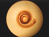
Almost close enough, but field askew so rocking needed. Also indication of lateral adjustment is required to even up illumination.
Signs here though of a field not fully covered by the
condenser. A positive lens underneath the latter needed to correct this.*
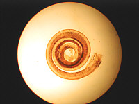
Field almost centred, but lateral displacement of camera required to correct off axis illumination.
Also signs of camera being either too near or too far
from eyepiece.
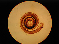
Better than above, but a fraction out laterally and proximity to eyepiece.
A whisker off axis laterally, field OK, but definitely a problem with proximity to eyepiece again.
Narrowing the substage diaphram helps in this situation,
causing the camera's iris to widen and make alignment a little easier.
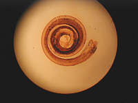
Evenly illuminated, though field a whisker off, but not important. This image was used to produce the one below.
*A common problem with low to medium power is a reduced illuminated field. A quick remedy is to put into the optical path below the substage condenser (or filter holder ) a positive lens of about 3" focal length, which will provide a bright field to the edges in almost all situations.
Moth's Tongue after cropping, sizing, sharpening, and colour correction to neutralise the colour of the aging balsam ....(slide about 100 years old ). The specks in the outer field were 'swept' to facilitate compression for the web.
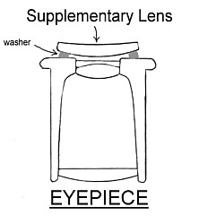
Increasing image scale on digicam CCD's If you have a fixed focal length camera like mine, and only one eyepiece, and no tube length adjustment, there are times when a larger image scale on the CCD is required to reveal more detail, especially if you do not want to use a higher power objective and risk decreasing the depth of focus. A small positive lens of about 1-3" focal length placed directly on the eyepiece as shown will accomplish this. Top eye lenses from old Huygen eyepieces work well too, though low power types are better in practice providing a more accessible image for the camera's lens, which in some cases might be very close, so care is required.
Care must be taken with the eyepiece's top lens to avoid contact with any other element, making provision to separate the two lenses with small paper or fibre 'washer' if necessary before taping on. Best results are usually obtained when the lens is orientated as shown, i.e. steeper curve down.
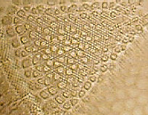
Actinoptychus heliopelta. Using 40X phase obj. and 10X eyepiece. Image left shows Olympus 830L's image with the normal setup, and on the right after about 100% image expansion with an achromatic 'eye' lens from a 20mm telescope eyepiece (Kellner). The original image left has been sized up to facilitate comparison. Both images have been treated equally in processing, but the difference is instantly obvious, and demonstrates the advantages of such a simple technique.
All comments welcomed, please contact Paul James.
Published in the January 2000 edition of Micscape Magazine.
Please report any Web problems
or offer general comments to the Micscape Editor,
via the contact on current Micscape Index.
Micscape is the on-line monthly
magazine of the Microscopy UK web
site at Microscopy-UK