|
First steps in exploring epi DIC (on a Zeiss Photomicroscope)
by David Walker, UK
|
I was fortunate to acquire a used transmitted Nomarksi Differential Interference Contrast (DIC) outfit for my Zeiss Photomicroscope III a few years ago and enjoy using it as a complementary technique to other methods of contrast enhancement such as phase and oblique. The capabilities of the technique for studying subjects such as certain aquatic microscopic life is well known and striking imagery has been shared by Micscape
contributors including Wim van Egmond, Spike Walker and Richard Howey. For me, the potential uses and capabilities of reflected light DIC (i.e. incident / epi DIC) in a hobbyist environment wasn't that clear and I invested in two suitable epi objectives to try the technique. My naive studies on what subjects epi DIC was best suited for may be of use to others equally unfamiliar with the technique, so my early explorations to date are shared below.
epi DIC requirements cf transmitted DIC
The requirements for epi DIC if an epi head is already owned are simpler than for transmitted DIC and thus potentially less expensive. Unlike for transmitted DIC, a single prism above the objective acts for both beam splitting and recombination. As with other incident axial light work, the objective also acts as its own condenser. Different makers' implementation of the technique likely differ and only how it is practiced on the Zeiss 160 mm tube length system optics on a Zeiss Photomicroscope
is shown below. I already owned an epi head, polariser and analyser and so the only additional requirements were one or more Zeiss Epiplan POL objectives each with their matched prism. I decided to buy a low power and dry medium power example to explore different aspects of the technique and chose the 4x NA0.10 and the 40X NA0.85—each with their prisms were a comparable price on eBay to the equivalent transmitted brightfield planachromats, possibly because of the lesser interest in incident light work.
|
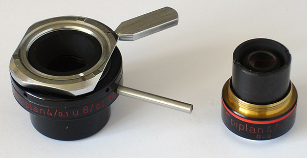
The Zeiss documentation states that the Epiplan Pol range of objectives are used for DIC when each are matched with the correct INKO prism.
Right: The Zeiss Epiplan 4/0.10 Pol objective disassembled from its INKO prism and mount. My example is labelled for DIC; I'm not clear whether DIC labelled examples differed in any way to the Pol. This INKO mount is labelled as being also suited for the 8/0.2 objective.
The bar on the prism only translates the prism in the x-y plane to change the amount of so-called bias retardation.
(I believe some makers e.g. Reichert used a single prism for their epi DIC objective range and the prism block also had facilities to adjust the prism vertically to set the correct plane with respect to the back focal plane of each objective.)
|
|
|
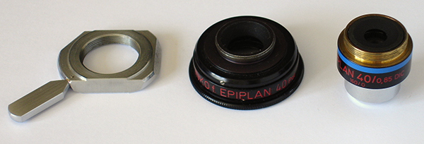
Right: The Zeiss INKO Epiplan 40/0.85 DIC disassembled from its prism and mount. On this objective the prism is translated by rotating the knurled ring on the prism mount.
Note that the two objectives shown use different sized threads in the dovetail mount (RMS and M24).
|
|
|
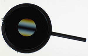
Right: The prism of the 4X objective between crossed polars. The typical central black bar of zero interference and higher order spectra of a Nomarksi modified Wollaston prism are shown. When first installed on the microscope, the correct orientation of the black bar (45° to the E-W axis between crossed polars) should be checked using the Optovar or a phase
telescope as described in the manuals. On my example it was not initially 'set' correctly in its dovetail mount.
|
|
|
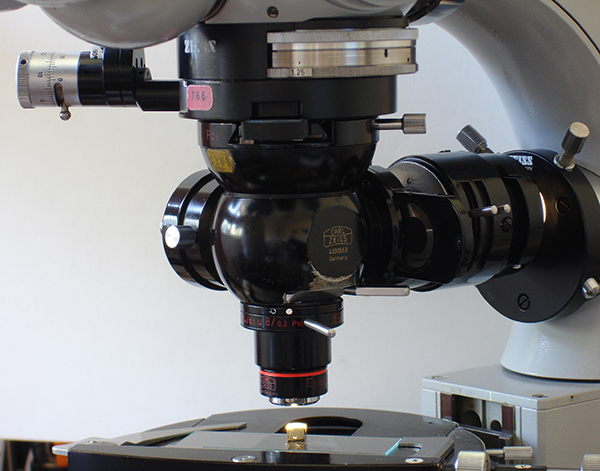
Right: A Zeiss Photomicroscope III set up for incident / epi DIC. Mine has the single objective epi head IIC, a turret model was available. The 4X objective is in use studying a cube of iron pyrites. Placing small items for study on a blank microscope slide allows the mechanical stage controls to be retained.
A polariser sits in the lamp optics to right and an analyser is fitted in the upper slot (a variable one show here isn't vital if the polariser can also be rotated manually to set full extinction).
On the Photomicroscope, a lever on limb allows quick change from transmitted to incident light use. Unfortunately the epi condenser for the Photomicroscope shown fitted, seems very hard to source (the Universal uses a different design), it took me five years of searching to find one. Although prior to that, a right angle prism sitting on a card mount within the port worked well. The Zeiss side bar lamp support
that fits in epi port may also work but the rear fittings of the epi head need removing to allow clearance for it.
The reflector in the epi head is quickly interchangeable (the drum with knurled nut just above objective and facing to rear. My example has the H-Pl reflector (a half silvered mirror) which Zeiss do state is suitable for DIC but remark that the H-Pl Pol reflector (a double reflecting design with both a half-silvered and fully silvered mirror) is better because the former suffers from some depolarisation.
|
|
|
The theory and general practice of reflected light DIC is very well explained and illustrated on the Molecular Expressions website. Its implementation on Zeiss 160 mm tube length microscopes is described in the Zeiss literature of the time, most of which is available online (see Resources).
Essentially the typical subjects should be reflective, flat and usually opaque. epi DIC can reveal fine changes in surface relief and surface composition. Unlike in transmitted DIC, the 3D imagery if correctly interpreted is an indication of the surface topography.
One of the classic and most illustrated examples of its professional use is in metallurgy of prepared polished, sometimes etched, metals and alloys. I don't have access to these type of samples unfortunately at present.
The technique is also widely used for studying electronic components such as silicon chips during and after manufacture.
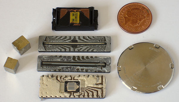
Right. Some typically suitable subjects from my own studies. Minerals with essentially flat reflective such as the faces of iron pyrites, electronic components (a B/W and colour sensor from old handheld scanners, the electronic plate from an old inkjet cartridge and an exposed EEPROM chip are shown). Engineered metals such as coins, watch parts etc.
Exposing the chips of integrated circuits can be tricky and needs care especially if mounted in hard, brittle ceramic substrates. Trace toxic elements may also be present.
|
|
|
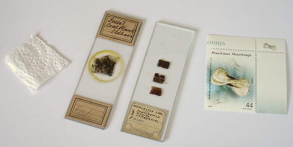
Examples of subjects that were not suitable are shown right. Paper and textiles have plenty of surface texture, can be essentially flat but unsuited if not reflective. Selected areas of paper or plastic goods which are reflective can work e.g. the hologram areas of credit cards, security features on bank notes etc.
The uncovered coal slide shown had a matte unpolished surface and gave poor images. Polished examples may work better.
Although the right-hand coal section was uncovered and did contain fossil micro structure, it had a none reflective, coarsely ground surface.
|
|
Covered subjects? As epi DIC is a reflected light technique, it wasn't clear to me if an otherwise suitable subject becomes unsuitable if covered, e.g. if already mounted on a slide under a cover slip. To assess this I took a subject which revealed plenty of detail with epi DIC, a cube of iron pyrites, and studied before and after covering with a slip and using water
as the mountant. There was no evident loss of image quality or detail or evidence of flare in this example. 'Try it and see' seems a good approach with a subject if uncertain, although many of the typical subjects of prepared slides i.e transparent and non-reflective are not suitable. The covered example of the coal section in the image above was also unsuitable as it had low reflectivity.
A potential problem of suitable covered samples, assuming the cover does not interfere e.g. if birefringent, is that the cover thickness (or air gap if a dry deep cell) may not allow the use of medium to higher power objectives with a small working distance. This problem occurs with the 40/0.85 objective owned (working distance W.D. 0.23 mm from Zeiss specs) if trying to study digital camera sensors with the front filter
/ dust plate present or studying one of the classic subjects—the digitally encoded layer of a CD/DVD. The latter sits too far in to focus and needs careful preparation of the subject, which has eluded me to date. (A 20-25X high NA objective with higher W.D. may be useful in this regard and have successfully imaged the layer of an unmodified CD with a 20X brightfield objective and off-axis illumination.)
A selection of images with comments
|
|
|
|
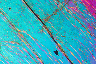
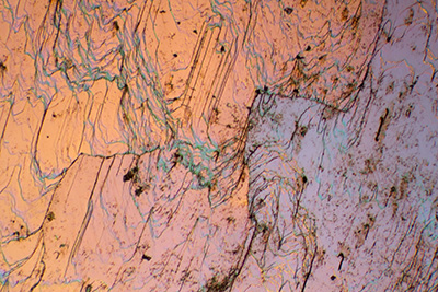
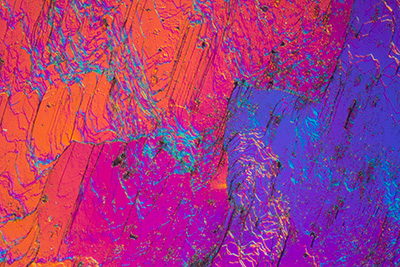
Iron pyrites face of cube, 4X objective, horizontal field width (HFW) 1.7 mm. To the eye the faces are essentially flat.
Top left: analyser omitted, i.e. effectively axial epi illumination without DIC. The crystal boundaries are clearly seen but no clear relief information.
Top right: epi DIC with bias retardation minimal, i.e. prism set centrally. Although not as clear on the image, seen visually, there is a distinct three dimensionality with a 'cliff type' boundary across the diagonal where there is a marked change in surface relief.
Bottom right: epi DIC with strong bias retardation set by moving prism laterally. The changes in relief are highlighted in colour.
|
|
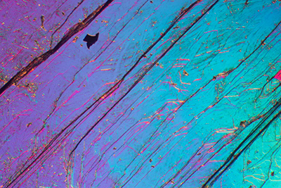
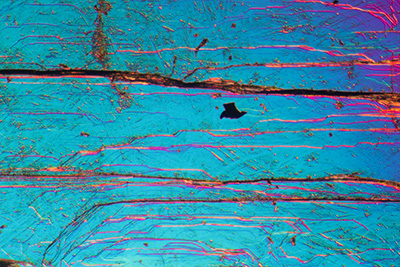
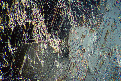
Above four images: Iron pyrites face of cube, 4X objective, horizontal field width (HFW) 1.7 mm. Different area selected, all images epi DIC
As in transmitted DIC, orientation of the specimen features with respect to the shear axis (which runs NW-SE in all images) can be varied to optimise the detail that is of interest. A rotating stage is valuable for orientation studies.
Top left: crystal boundaries parallel to shear axis of prism.
Top right: crystal boundaries at right angles to shear axis.
Bottom left: crystal boundaries at right angles to shear axis.
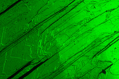
Bottom right: crystal boundaries at right angles to shear axis with monochromatic green light using an interference filter. Although the interference colours can be attractive, the surface topography for this subject seems clearer and in higher contrast with monochromatic light.
| Right: 4X objective, HFW 1.7 mm. epi DIC. Circuit board from an old inkjet printer cartridge, the style where the jets were in the cartridge. |
|
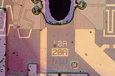
| Right: As above except the analyser was taken out, so effectively axial epi brightfield illumination. The surface relief details on this circuit board are very subtle and the relief information revealed by the DIC wasn't that marked. |
|
|
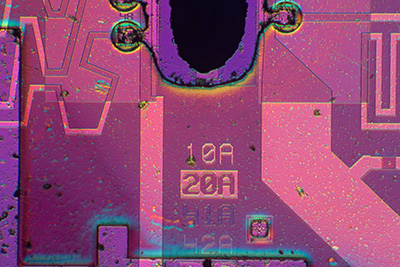
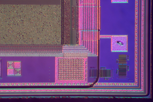
Right: 4X objective, 2X Optovar. HFW 1.1 mm. epi DIC. Corner detail from the digital sensor on an old monochrome security camera.
The imaging area is top left, supplementary circuitry and what may be alignment marks for manufacture are show on the periphery.
The sensor still has its dust plate on, but the long working distance of the 4X objective could focus through to the sensor. This was not possible with the 40X objective. There was evidence of contrast loss because of the dust plate, but levels adjustment in image editing software corrected for this.
|
|
|
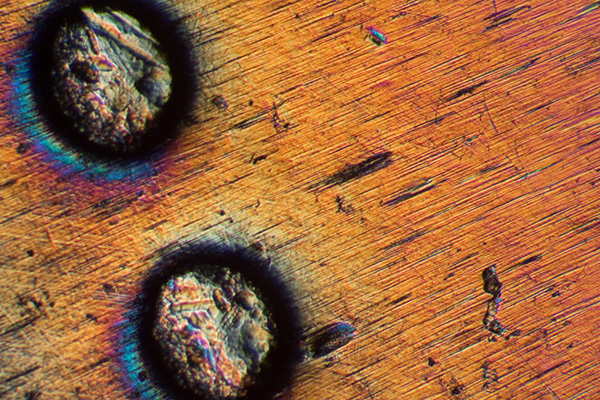
Right: 4X objective, 2X Optovar. HFW 1.1 mm. epi DIC.
Mint Canadian Trade Dollar (Niagara Falls). Area of the highly polished 'silver' coin base and some dimples around the edge. epi DIC is not designed to study gross relief found on subjects like this coin, off-axis incident lighting is adequate for this. epi DIC is more suited for revealing the finer surface relief e.g. in this case on the coin base, which to the eye is near featureless and highly polished.
|
|
|
Right: 4X objective, 1.6X Optovar. HFW 1.35 mm. epi DIC.
Edge detail from the sensor of an old handheld scanner, shown earlier as the thin strip in the collage of suitable subjects. The sensor area is out of shot, the ancillary circuitry and likely alignment / calibration marks are seen.
|
|
|
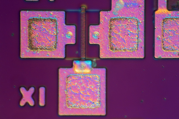
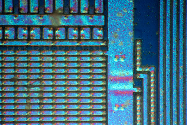
Right: 40X objective HFW 0.19 mm. epi DIC.
A powerful feature of transmitted DIC is its ability to optically section, which can be very useful e.g. for studying important features of microorganisms such as surface cilia on some protists.
Optical sectioning also applies to epi DIC and can be useful in industry for studying selected complex layers of an integrated circuit.
The image right shows circuit detail of the monochrome handheld scanner sensor. One layer of tracks is picked out in focus, a lower layer is not in focus.
The optical sectioning can be a disadvantage in photography where stacking may be needed to capture all the features of a subject in a single image.
|
|
|
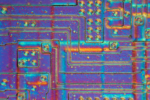
Right: 40X objective HFW 0.19 mm. epi DIC.
Circuit detail of the monochrome sensor from a handheld scanner.
|
|
|
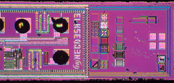
Right: 40X objective HFW 0.19 mm. epi DIC.
Right: An exposed EEPROM chip. The block of programmable memory which is erasable by UV light is seen bottom left.
Experimenting with both the rotation and extend of bias retardation can reveal which combination best shows the features of interest.
|
|
|
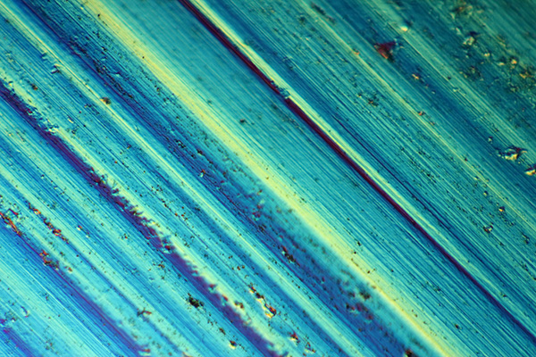
Right: 40X objective HFW 0.19 mm. epi DIC.
The ability of epi DIC to reveal the finest surface topography in subjects which seem almost featureless to the unaided eye, is perhaps best illustrated with this familiar household example of unused aluminium kitchen foil cut straight from the roll.
The right-hand image shows the polished side and reveals the marks during manufacture.
|
|
|
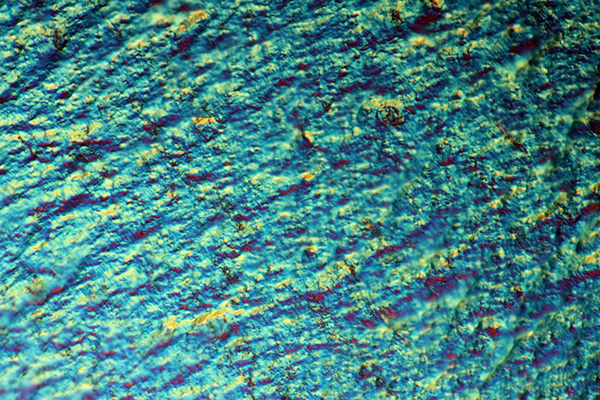
Right: 40X objective HFW 0.19 mm. epi DIC.
Aluminium foil on the matte side showing the complex disordered surface relief associated with this finish.
To what extent a surface becomes unsuited for epi DIC because it is either too matte and/or its colour, I'm uncertain as the matte side of the foil has low reflectivity. A matte coal section with microfossils tried showed very little under epi DIC (although of course is much darker as well as having little reflectivity).
|
|
Comments to date
Exploring with epi DIC has certainly to date been very enjoyable and interesting with the suitable subjects being very different from those where transmitted Nomarski DIC is useful. The low power 4X and 40x objectives seem good choices for studying a variety of subjects at low and medium powers. Although have found the low working distance (0.23 mm) of the 40X NA0.85 to be limiting at times e.g. for subjects like a CD or covered sensor. The LD Epiplan Pol 40X NA0.6 with greater working distance (3.4 mm) at
the expense of NA could be useful.
Aspects of microelectronics yield particularly attractive imagery, although unless familiar with integrated circuit construction, the hobbyist like myself finds them interesting rather than being able to learn from them. It's a pity polished and etched metallurgical specimens aren't more readily available as that seems an area that offers an opportunity to learn about aspects of metallurgy as well as affording often spectacular
imagery.
Comments to the author David Walker are welcomed.
Resources for DIC implementation on Zeiss 160 mm tube length microscopes. (Content remains the copyright of Carl Zeiss.)
Microscopic contrast enhancement methods. Transillumination. Operating Instructions Carl Zeiss pamphlet G 41-211/l-e (also covers phase and darkfield).
Handbook of incident light microscopy. 1. Qualitative microscopy by Dipl.-Min. W. Cebulla. Carl Zeiss 68 page booklet K 41-003-e dated August 1980. (With thanks to a fellow enthusiast for donating the booklet.)
Zeiss Optical Systems for the Microscope (Hosted on Gordon Couger's science-info.net website.) The essential 97 page 'bible' for the optics of the 160 mm tube length models. Includes the full range of Epiplan Pol objectives used for epi DIC.
Zeiss Support web page. Hosts various operating instructions for older Zeiss microscopes. Of particular relevance is the 'Photomicroscope III, Incident Light' manual which describes the various epi heads.
©
Microscopy UK or their contributors.
Published
in the July 2013 edition of Micscape.
Please
report any Web problems or offer general comments to
the
Micscape
Editor
.
Micscape
is the on-line monthly magazine of the Microscopy UK web
site at
Microscopy-UK
©
Onview.net Ltd, Microscopy-UK, and all contributors 1995
onwards. All rights reserved.
Main site is at
www.microscopy-uk.org.uk.