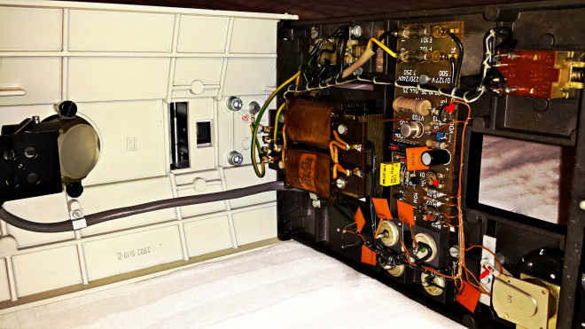
Zeiss Laboval 4, base open to show illumination power supply
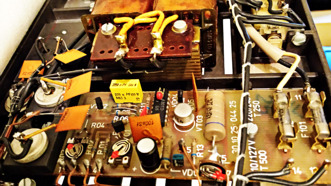
Closeup of
power supply circuit board – four transistors, one integrated circuit, two
fuses, three trim pots,
and four round gizmos that I cannot identify (left side
– bridge rectifier??).
... and all to light one little bulb
This article continues from Part I, which discussed repairing the illumination control circuit of the Nikon S, as well as similar very early electronic microscope power supplies. Here, we discuss the principles behind more modern microscope illumination systems and suggest fixes for blown lighting circuits in scopes of this vintage.
The simple fix described in Part I worked well for the uncomplicated, 1970s-era intensity control circuit on the Nikon S, and will probably be applicable to similar early microscope illumination systems. Unfortunately, the greatest number of quality used microscopes are of more recent vintage, use more complex electronic control systems, and are more of a challenge to repair.
Removing the base plate from a newer generation microscope will likely reveal a printed circuit board bearing a number of small capacitors, resistors, coils, transistors, and integrated circuits. The Laboval 4 power supply shown above is complex, with some very Russian-looking components. Built in East Germany in the late 1980s to early 1990s, the Laboval 4 is built like a Russian tank and has excellent optics – but buying replacement electronic parts would be almost impossible. You can see why a scope of this type would be scrapped if the power supply blew.
Besides, what do all of these electronic gizmos have to do with running a light bulb? I must admit to having had almost complete ignorance about electronic microscope power supplies, and yearned for a good old autotransformer that could break a toe if dropped. However, if your power supply dies and you are faced with repairing it or spending bucks for a new scope, don’t give up. That small, mysterious printed circuit board in the base uses very standard circuits, and the supply can be rebuilt or replaced more easily than you might think.
DEVELOPING THE NEW INCANDESCENT POWER SUPPLY:
In the decade after the Nikon S-Kt, microscope manufacturers worked hard to cram a smaller but equally powerful illumination system into the microscope base and eliminate the external supply. Since the transformer is the largest and heaviest element in the illumination power supply, this meant reducing transformer size while maintaining capacity.
The solution was the so-called “electronic transformer” – actually a misnomer for a “switch mode power supply” or SMPS. Don’t let the fancy name scare you; this type of power supply arises from an ingenious but simple concept and is made from basic circuit components. The essential idea is that the size of a transformer, for a given wattage, is inversely proportional to the frequency at which it operates. So a transformer operating at 300 Hz (or 300 cycles/second) can theoretically be 1/5 the size and weight of a similar, old-fashioned unit working at 60 Hz, or AC line frequency.
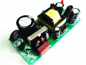
![]()
220 to 12 Volt “Electronic” Transformer. This is only a few inches long and weighs a few ounces.
This type of power supply operates by transforming 110V or 220V line AC into direct current, and then transforming it back into alternating current via a simple transistorized switching circuit – but at a higher frequency. This “re-manufactured” higher-frequency alternating current can then go through a smaller and very efficient transformer to be stepped down to a lower voltage suitable for powering an incandescent or halogen lamp. Many of the small supplies work at quite high frequencies of 20,000-50,000 Hz; they are thus quite efficient, and any interference signals produced are well above the threshold of human hearing.
The circuitry for rectifying the AC current to DC and then”inverting” it back to higher frequency AC that can be re-converted into whatever you need (much like the 12V to 110V inverter one buys at the hardware store) is light and compact, and the final transformer is a fraction of the size and weight of an old 60 Hz unit. The AC ==> DC ==> high freq AC ==> low voltage AC transitions for lamps are handled on a board a few inches long and weighing only a few ounces. For incandescent or halogen lamps, the low voltage output can be either alternating or direct current – lamps with filaments aren’t fussy about what they eat for dinner. For a direct current-only device, a final step is added in the form of a second bridge rectifier to convert the low voltage AC into smoothed DC:
Simplified circuit for a DC output switch mode power supply, with second bridge rectifier converting low voltage AC output to low voltage DC
The filter capacitors store energy as the rectified direct current pulsates, taking in energy during the peaks and releasing it in the valleys, much as an old-time millpond provided a constant flow of water to the mill’s water wheel. The result is a smooth direct current output voltage.
THE UBIQUITOUS SMPS – BUT:
Since solid state components (integrated circuits, transistors, and diodes) can now be mass-produced for a few cents, tiny SMPS power supplies are so cheap and convenient that they are used for supplying most small electronic devices – battery chargers, cell phones, tablets, clocks, lamps, etc. – and most households have at least a dozen hiding in wall sockets and behind bureaus. A home with many electronic gizmos may have a hundred of these small devices. In electronic slang, the small, socket-mounted variety is called a “wall wart“. This derisive moniker arose from the tendency of the older, larger chargers to eat up space on wall sockets and power strips, and to be heavy enough to fall out onto the floor at intervals, crashing the instrument they were supplying. Today’s socket-mounted SMPS chargers are much smaller and lighter than the “linear” designs of twenty years ago, which, using a bulky transformer followed by a rectifier and filter, often drooped from the socket.
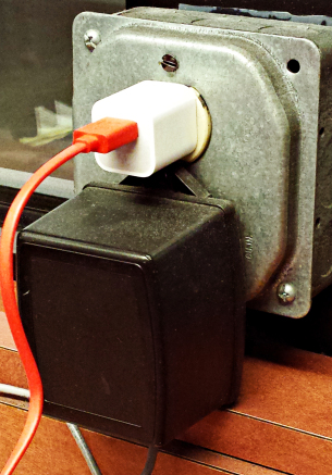
“Wall Warts”: Old linear transformer-based power supply (bottom) drooping
from the socket, versus contemporary tiny iPhone SMPS (top)
One should not, however, disparage the older “linear” power supply. The term “linear” refers to a supply that, unlike the SMPS, does not convert and reconvert electricity from AC to DC to AC, changing the type of current AND the frequency AND the voltage. SMPS supplies have taken over in most consumer applications because of their small size, light weight, low cost, and high efficiency. However, their components are constantly working as tiny switches; they consequently have a higher noise level and poorer voltage regulation. The older “linear” (transformer ==> rectifier ==> filter) supply, named because its components are operating in the linear phase of their operating curves, is inherently heavier and produces more heat, but has less noise superimposed on the output current, better regulation, and faster recovery from transient spikes in the line voltage. They are still used where very pure, low noise, very tightly regulated current output is required. A chart comparing the features of the two systems can be found on the Acopian site.
From a microscopist’s standpoint, the tiny but powerful SMPS supplies and halogen bulbs resulted in leaner, lighter scopes and brighter lighting without bulky power transformers. HOWEVER, the downside of this innovation was that those clunky but durable transformers were replaced by electronic components with a much more uncertain lifespan. These may be difficult to replace after a few years have passed (one service specialist struggles to find parts for some twelve-year-old models), and the first generation of these electronic systems is now approaching the 50-year mark.
REPLACING A DEFUNCT LIGHTING SUPPLY:
One has three alternatives to repair a blown electronic power supply: move to a simple external supply, buy a power supply that will fit, or custom-build a small supply and control unit that fits into the same space as the old unit. Building an external supply was discussed in Part I – a cheap dimmer driving a 6V or 12V transformer, possibly of type used for a doorbell and available from a local home supply store. Buying a new power supply is easiest, and these are cheap and standardized – this small SMPS works on 85-265V AC input, puts out 12V DC at one ampere, and costs $8.40 on Amazon Prime:
One may have to figure out how to tie the microscope’s light intensity control potentiometer into the circuit, but this is a cheap, prepackaged fix if the supply fits the space available in the base. These small power supplies are available from online stores in a wide variety of combinations of wattage and output voltage. A few have the dimming function already built in, and are intended as replacement power supplies for single halogen bulbs:
6 Volt, 30 Watt Dimmable Halogen Lamp Replacement Power Supply, $22.99 on eBay
If you do buy a generic power supply, try to pay a bit extra and get it from a reliable manufacturer. There are many cheap electronic devices available in the online market, but many of these are of overseas origin, poorly-constructed with substandard components, badly designed, and pose a shock hazard (see Elliot).
One very cheap solution is to look for an old computer or printer power supply in an appropriate voltage. This may take considerable ingenuity and searching, but these can be found readily at thrift shops or Salvation Army stores. Depending on the supply’s circuitry, its output may be dimmed either with a low-resistance rheostat on the low voltage side, or an appropriate 110 or 220 volt dimmer on the line side. The supply can either be mounted in its plastic case, or opened and the circuits removed. An older, linear-type supply may be easier to dim. It may be necessary to try two or three thrift shop power supplies until you find the one that works. You might even consider buying an old, variable-intensity halogen desk lamp at the thrift store and transplanting the power supply.
BUILDING A REPLACEMENT LAMP POWER SUPPLY:
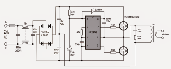
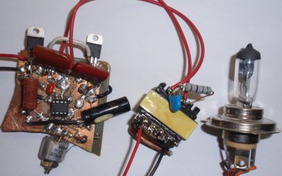
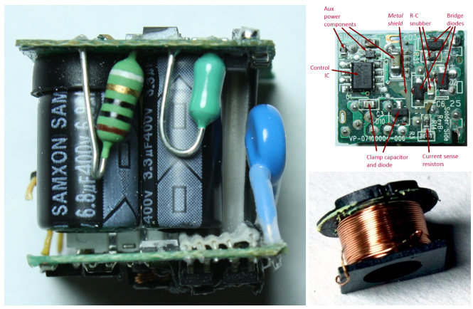
Rebuilding the power supply or building it from start is a bit more challenging, but can be done even with modest electronic experience. You may be able to clean off and use the appropriately-shaped circuit boards from the old illumination system. Depending on the illumination system of the microscope, there is a multiplicity of adaptable basic circuits on the internet; these may use two transistors, thyristors, or a small integrated circuit for the switching circuit, as there are a number of ways that this simple circuit can be set up. The circuit below uses a bridge rectifier (left side) to produce DC from 220V mains AC, then employs an IR2153 integrated circuit and two IRF840 MOSFET (Metal Oxide Semiconductor Field Effect Transistor) devices to chop the DC to rapid frequency AC; the latter is then stepped down by the small transformer on the right to light a halogen bulb.
Given the many variations in space and circuitry used by microscope manufacturers, there is no single fix that is adaptable to every vintage scope. Building a replacement illumination supply will take a bit of ingenuity and perhaps a visit to your local electronics store (NOT the consumer radio store in the mall – you need a REAL electronics store with racks of equipment and perhaps a bit of dust in the corners). Which circuit you use will depend on available materials and components, what kind of advice you find, where you live, and how much power your light needs. Finding a truly simple dimmable power supply circuit for a single halogen bulb is not an easy task; the above circuit is one of the least complex. But actually constructing one of these power supplies is not rocket science and can even be done as a first electronics project.
YOU TOO CAN DO THIS:
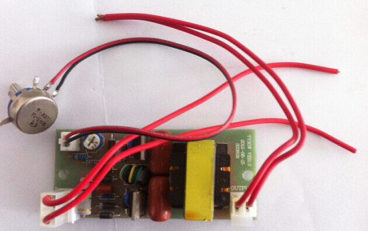
This is an example of a tiny, home-made halogen lamp SMPS power supply – look closely and you will see that the wiring and soldering are pretty rough, but it works:
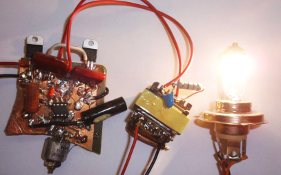
This small, home-made switch mode lighting circuit supply uses two thyristors (or possibly MOSFETs, they all look similar) and a small integrated circuit. Note how compact it is – this should be able to be fitted into the limited space in a microscope base and work with the old bulb and lenses.
Sixty years ago, this unit would have been completely impractical, with vacuum tubes and their power supplies occupying the space of a packing crate, the unit weighing 70-100 pounds, consuming more electricity to heat filaments than it produced, and
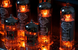
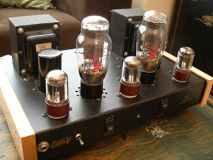
emitting enormous amounts of heat. It is a testament to modern microelectronics that it is practical to convert and reconvert power several times in this manner, and that the process can occur in a packet the size and cost of a box of lozenges.
For those to whom this is all new information, the concepts behind the electronic power supply are very simply and coherently explained at the Williamson Labs’ site.
Note this especially: If you think that this is all a long way from looking at small wriggly things and batting mosquitoes in the swamp, you are right. A quick look at the specification sheets above for components like the IC and the MOSFET rapidly convinced me that I’d rather just sit back and applaud than try to understand what’s happening in all those little black thingies. BUT – if this lets me buy a research-level Zeiss or Olympus with blown electronics for $200, and then have it sitting on my bench to use every day, it’s worth it. And you don’t really have to understand it, except in a general sense. You just have to know enough to solder together the wires and close up the case.
If, however, you are inspired to learn more about these ubiquitous and amazing little devices, read Ken Shirriff’S dissection of the Apple iPhone power supply (the little white cube in the above image). His description of how an SMPS (including transformer ), with sophisticated voltage regulation and overload protection, is compressed into a one-inch plastic cube is fascinating. The images below are courtesy Mr. Shirriff:
The images above show how ingeniously every cubic millimeter was used in the iPhone cube, as well as the sophistication of the SMPS circuitry to handle a variety of loads with reasonable regulation in such a tiny space. Fortunately, microscope illumination systems can be much more basic and much less space-intensive, with simple circuits that do not need to adapt to such a multiplicity of circumstances.
Hopefully, this information will take some of the mystery out of microscope power supplies. I wonder how many sophisticated microscopes have gone into the junk bin or been broken up for parts because the owners assumed that a busted power supply was irreparable? I would like to have suggested one simple, all-encompassing solution that would replace the power supply for all of the “semi-modern” microscopes that are new enough to have electronic lighting supplies, yet old enough that parts are no longer available.
Unfortunately, what will work as a replacement power supply is dictated by space, the power and voltage requirements of the bulb, the materials at hand, your experience with tools, and, ultimately, your budget and patience. There is no single universal fix. Ingenuity and backwoods improvisation are often the essential elements to salvaging a sophisticated scope with bad electronics. The point is that these power supplies from 20-30 years ago can be replaced or rebuilt, and they are not mysterious, irreplaceable devices. If you have an idea of how these circuits work and are willing to dive in, your reward will be a functioning, classic microscope and the satisfaction of having a fine piece of equipment that you have restored.
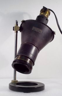
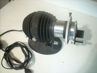
When things were simple: antique microscope light sources – Spencer on left, AO on right
This article is continued in Part III, which deals with LED conversion. We will review the construction and function of light emitting diodes, discuss how to power and regulate them, learn why they are NOT light bulbs, and include some of the few articles describing how classic scopes have been adapted to use LEDs.