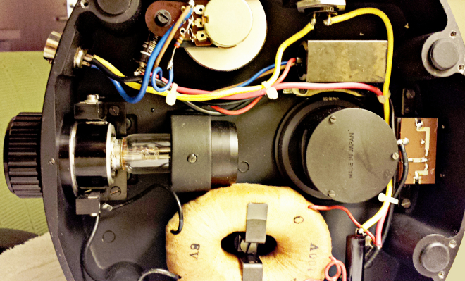
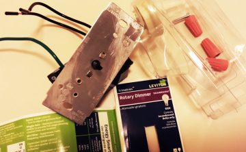
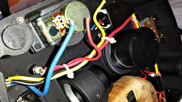
Nikon S-Kt illumination system, base removed. Note old-style “toroidal” transformer at bottom and voltage adjusting potentiometer at upper left. The toroidal design is actually highly efficient and shows less power loss than square designs. The thyristor (Triac) is the pillbox-sized rectangular structure at upper right. Someone has improperly rewired the potentiometer at upper left – note bare wires!
Restoring my beautiful old Nikon S proved to be a continuing saga – and a remarkable learning experience. In my last article, I described the procedure for replacing a broken nylon fine focus spur gear, a problem that has sidelined many of these finely-crafted old scopes.
I originally bought the Model S-Kt with lenses (in lovely shape from 20 years on a shelf) for only $75 because the light would not turn on. Getting the light working took only ten minutes with a soldering iron to re-secure a loose flange on the light bulb, after which the bulb connected properly. However, deeper problems lurked within. After repairing the focus gear and bulb, using the newly-restored scope revealed that the bulb voltage could not be raised over two volts and the transformer was overheating and smelling hot. It was unclear whether the transformer was shorted or the electronics were not working.
This question was solved when, after half an hour of operation, the light suddenly flared to its full brightness and the intensity control stopped working. Clearly, the transformer was producing full voltage, but the 45 year old electronics had blown. Removing the baseplate revealed homemade circuits on the intensity control potentiometer; these may have contributed to the overheating and failure of the old circuits.
I knew nothing of light control circuits, but online research informed me that the core of a light dimmer system was something called a thyristor. So what is a thyristor, and what are those mysterious little thingamagummies on the printed circuits inside the base of any but the oldest microscope power supplies? I had to educate myself in the history of microscope illumination, and it turned out to be a fascinating journey.
THE ELECTRIC BULB AND THE DIMMER:
(With thanks to Mark Morris for suggesting this fix)
In the 1950s and 1960s, microscopes typically had external power supplies for the illumination system. These usually had no electronic components, and relied on an autotransformer, or variable transformer, to control light intensity. The latter is a simple device, with a single winding on a circular core, and a moving contact to take off a variable secondary voltage for the bulb. Autotransformers are primitive, heavy, clunky, and much too large to fit into a microscope base – but they are also simple, sturdy, and almost indestructible under normal conditions. And when one did (rarely) short out, you tossed it into the trash, bought a new one, plugged it into the scope, and went on with your day. The insides of the microscope contained a bulb, a mirror and sometimes a few lenses, but little else. With the exception of dirty contacts or broken cables, these simple systems could be expected to function reliably fifty years after they were first turned on.
![]()
Old Nikon Autotransformer Illumination Control
As microscopes became more streamlined, power supplies moved into the base of the scope and incorporated newer, more compact electronic control systems made possible by the advent of solid-state electronic devices.
Controlling electric current electronically is not a new idea. In 1906, Lee De Forest invented the “Audion”, the first functional vacuum tube; this design and its basic theory was later improved by Fleming. Electrons boiled off a hot filament flowed to a positively-charged second electrode (the “plate”). A small negative voltage applied to a thin mesh (the “grid”) inserted between the filament and the plate could control this relatively large current, thus allowing the tube to be used as an amplifier and heralding the beginning of electronic communications and controls (see De Forest’s original Scientific American article. However, vacuum tubes were fragile and wasted large amounts of power to heat filaments.
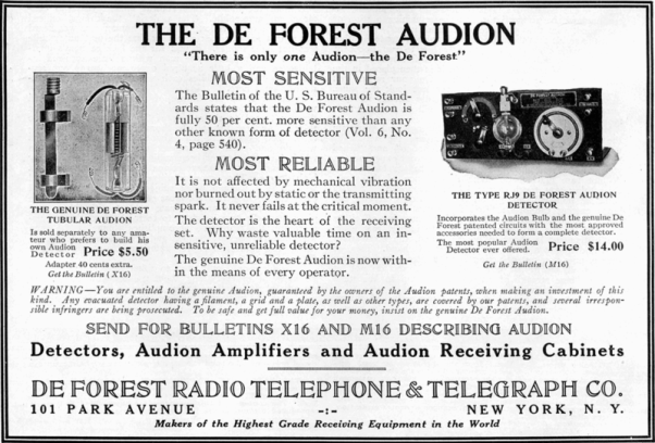
1915-20 ad for the De Forest Audion Vacuum tube
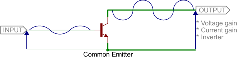
The transistor, invented at Bell Laboratories in 1947, uses three layers of semiconductor material to accomplish this function much more efficiently, with a small current applied to the “base” layer controlling a much larger current traveling from the “emitter” layer to the “collector” layer.
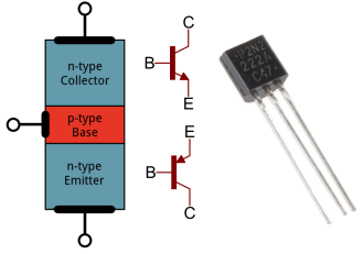
Transistor - courtesy Sparkfun
In solid-state devices, current can travel either as electrons or as “holes” – vacancies in atomic outer electron layers that act as mobile positive charges.
Transistor – courtesy Corollary Theorems
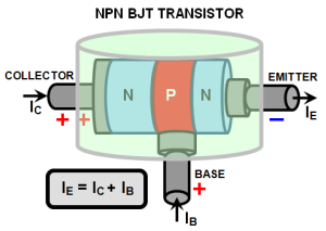
Current Amplification by Transistor – courtesy Sparkfun
In this way, the transistor, employing the base current like the grid of a vacuum tube, can perform the same functions as the vacuum tube, but with less weight, much less power consumption, lower voltages, and much smaller size. With choice of physical configuration and semiconductor material, as well as “doping” (addition of trace elements to the semiconductor material), an almost infinite variety of functions can be designed into semiconductors.
Model S microscopes were manufactured just as electronic controls were becoming available. Depending on the amount of space in the base, these microscopes employed either in-base, electronically-controlled power supplies (Model S-Kt) or older-style, transformer-based external supplies (Models S-Ke and L-Ke) if supplementary lenses and levers in the base left insufficient space for transformers and electronics. The electronic illumination control system in the Model S-Kt was simple – essentially the most basic of light dimmer circuits – but in the 1970s was considered to be very advanced:
“Modern, advanced semi-conductor technology has provided a facility for changing the flow time of electric means. A so-called thyristor of extremely small size has been developed to enable regulation of the brightness of the lamp. The Microscope Model S-Kt has adopted this type of light adjuster built in the microscope base.” (S-Kt Manual, Page 9.)
The heart of the S-Kt system, wall dimmers, motor controllers and many other electric power control devices is the thyristor, a solid state device very similar to the transistor but with one critical difference: while the current allowed to pass through the transistor is roughly proportional to the tiny current applied to the base, or control electrode, the thyristor (with leads designated anode, cathode, and gate) is completely non-conducting until a small current is applied to the gate, after which the thyristor flips fully to the conducting state. Thyristors therefore function as fast-acting electronic switches and, unlike the transistor, can easily control hundreds of volts and considerable current, even in high-power electrical transmission systems:
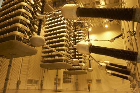
Thyristor valve hall at New Zealand power transmission station
Like the transistor, a thyristor is basically a direct current device. However, if one connects two thyristors in parallel but oriented opposite to each other with the gate connections wired together, one has a very functional, solid-state electronic AC switch: the Triac, or bidirectional triode thyristor. Furthermore, many triacs are not fussy about the polarity of the gating voltage, and can be switched on by either direct or alternating current, thus making the control circuitry simple: a small control voltage can be pulled off the main power supply, applied to the gate, and control a much larger current travelling between the cathode and anode. Although the theory and structure of triacs are complex, if one is not concerned about the niceties of symmetrical AC triggering, harmonics or very fine control (for example, with an incandescent bulb dimmer) the circuitry can be very simple:
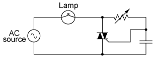
Simple Triac Dimmer. Capacitor helps control phase of gating current.
This circuit also demonstrates the simple concept of the basic incandescent dimmer, with the AC supply, the light bulb, and the triac dimmer wired in a simple series circuit. For a low voltage bulb, the primary of the bulb transformer can be placed where the bulb is in the circuit. Essentially, the triac acts as a switch, cutting out increasingly large chunks of the AC supply’s sine wave as the gating current and phase are altered by the resistor/capacitor combination. Chopping out pieces of the alternating current reduces the effective supplied power:
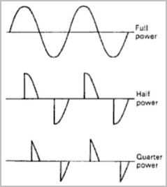
This system works well for incandescent lights, where the filament stays hot between pulses, effectively smoothing out any flicker in the illumination.
A SIMPLE FIX FOR AN OLD MICROSCOPE:
So how does one replace a 45-year old thyristor that belongs in a museum??? Excellent older microscopes (and many expensive and not-so-old models) are often sidelined because of failing electronic components and unavailable parts. This was becoming a thorny problem until Amateur Microscopy friends contributed ideas, and Mark Morris, who has been fixing these microscopes since I was in elementary school, gave me the key idea.
For $4.95, my local Home Depot gave me a cheap Leviton wall dimmer switch. Filing off the rivets and removing the case revealed the simple guts of the controller: a potentiometer, a small inductive load, two mica capacitors, and the tiny, all-important chip of a Triac thyristor:
Dimmer switch, front and with back removed. Note barely-visible, 1 cm square, black thyristor behind mica capacitor (small brown object)
Tracing the dimmer’s circuit shows it to be similar to the basic circuit shown above:

Circuit for the Leviton dimmer. The potentiomer, thyristor, and capacitor comprise the basic control circuit.
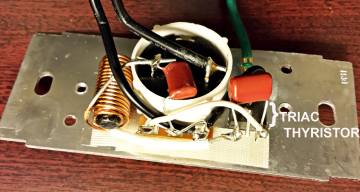
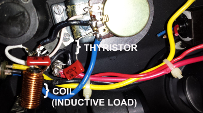
The potentiometer, thyristor, and small mica capacitor on the right comprise the control circuit, while the small coil and capacitor on the left limit interference from the switching process. As much as possible, these components were unsoldered from the dimmer potentiometer as a unit and reconnected to the intensity control potentiometer on the scope, thus maintaining the physical appearance and controls of this classic scope – the electrical equivalent of a heart-lung transplant. The original circuitry of the Nikon light controller was very similar and equally basic, but the 1970 thyristor’s volume was around 100 times greater than that of the tiny chip removed from the modern dimmer.
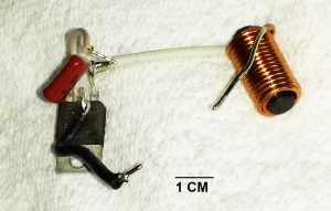
Some components of the Dimmer – thyristor, small ferrite core inductor (coil), and capacitor.
Cutting out the old thyristor
After the components of the dimmer were isolated, the wires to the old pillbox-sized Nikon thyristor were cut, and the hay-wired electronic components added to the Nikon light control system (trim potentiometer, capacitor, resistor, and connecting wires) were stripped out, leaving the Nikon potentiometer in place:
Nikon Intensity control potentiometer, all other components removed.
The tiny thyristor from the dimmer, which had a metal flange riveted to the dimmer’s front plate as a heat sink, was secured to one of the potentiometer mounting screws inside the microscope base, and the dimmer’s circuit was recreated using the Nikon’s potentiometer:
Dimmer components installed on Nikon potentiometer. Heat sink on the thyristor, the barely-visible black chip, is secured under one potentiometer mounting screw.
One of the problems with this “transplant” was that the Nikon potentiometer had a resistance value of 100K ohms stamped on one side, but the resistance of the Leviton dimmer potentiometer and the trim pot were unknown; this introduced a degree of guesswork into matching the two systems. When this configuration was tested, the Nikon bulb would only dim partially. Clearly, the amount of resistance provided by the Nikon potentiometer was less than the dimmer circuit was designed for.
With a considerable amount of hope and finger-crossing, the small trim potentiometer was soldered in series with the Nikon intensity controlling potentiometer. When it was turned on, the system worked perfectly! The trimmer’s resistance set the dimming range of the original built-in Nikon potentiometer; at one extreme, the bulb would not light at all, while at the other end of the trimmer’s range, the Nikon potentiometer could not dim the bulb fully. Using the trimmer near midrange, it was possible to set the range of the Nikon potentiometer to ideally cover the full dimming range needed for the bulb. This is the completed illumination control system:
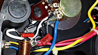
Completed control system. Range-setting trimmer pot soldered to left of main illumination potentiometer. Tiny modern thyristor barely visible below the trim potentiometer.
The completed Model S illumination control circuit with the new dimmer components is thus:

Final Nikon S illumination control circuit. Dotted line surrounds components transplanted from the dimmer switch.
This simple fix should work with older, 60 Hz illumination control systems based around a simple power control circuit and a transformer. It could also be used to replace a missing or non-functioning external transformer system: a dimmer switch and a 6 volt doorbell transformer in a small electronic case, with appropriate cords and plugs, could form a cheap and simple microscope light power supply. One could add a voltmeter and a little panel light to make it fancy.