An Inexpensive LED Cold Light

  By Andrew Entwistle

  USB Cold Light

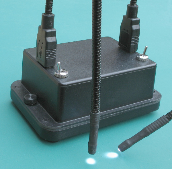
Fig. 1 An inexpensive LED cold light based upon USB powered flexible lights


Introduction

A few years ago, inspired by Rudolf Baumueller’s article I built a tungsten halogen fibre optic cold light (see fig. 2 below). It is very effective, but I have found that the fibre optic light guides are cumbersome to hold in position and the fan noise can get a little wearing after a while. Recently I noticed the availability of USB powered LED lights at the end of a flexible gooseneck. I realised that the slim gooseneck would be ideal for setting in a stable position and for getting light close in towards an object under the microscope. I saw this type of light on sale at a local ‘pound shop’ and saw an opportunity to experiment with them, and built a battery-powered base to power and support the lights. The total cost of the project was around £15.


Tungsten-Halogen Cold Light

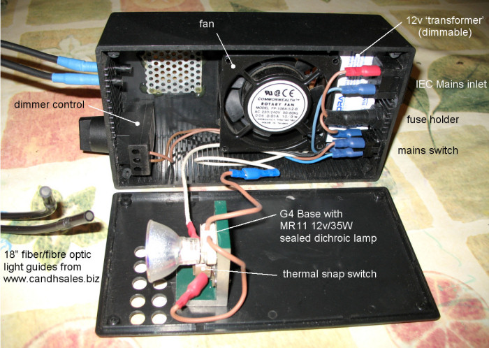
Fig. 2 Tungsten halogen fibre optic cold light. A dimmer control is used in conjunction with a low voltage lighting ‘transformer’ (actually a switched mode power supply) to drive the lamp via a temperature trip, in case of fan failure.


Modification of the USB LED light

One may find that modification of these lights is not necessary, depending upon their intended use. Despite these lights being selected wholly on the basis of their extremely low cost, the supplied white LED with diffuser is quite bright and has a wide enough illumination angle to be adequate for low power stereo work. However, I opted to remove the chromed barrel and to replace it with heat-shrink sleeving to give better access to the object illuminated. I also replaced the LED with a brighter, narrower emission angle LED giving sufficient illumination for work with a 40X objective. There is also the option to use different colours of LED.
USB Flexible LED Light

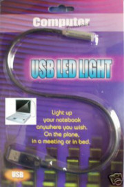
Fig. 3 A USB flexible LED light, available for £1 from ‘pound shops’ and for around £4 inc. P&P from eBay (May 06)

Referring to fig. 4 the stages of modification are as follows.

Modifications to USB LED Light

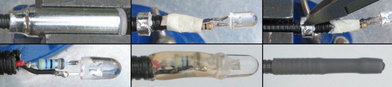
Fig. 4 The stages in modifying the LED light to have a slimmer profile and possibly an alternative LED

 
A Nichia 8000mCd white 5mm LED (N29AT from Maplin) was used to replace the original LED. A series resistor of 47ohms was selected to limit the current to the LED to its rated maximum of 30mA when used with a 5v USB computer supply. This also made it suitable for use with 4.8v from 4 x 1.2v NiMH rechargeable batteries. This choice does mean that use with 4 x 1.5v primary cells is prohibited, although 3 x 1.5v could be used with or without a more optimum resistor value. For other power supply options there are a number of Micscape articles covering the use of LEDs, for example, using a variable resistor to adjust the brightness. I prefer the simplicity of running the LED at maximum output which then produces a consistent colour temperature; the intensity to the viewer can be adjusted by altering the distance and angle of the light. The Nichia 8000mCd was later replaced with a 25000mCd white LED from www.besthongkong.com and a second assembly was made using a 395nm near-UV LED from the same source.


Construction of the powered base

Refer to figures 5 & 6. A rectangular hole was made at each end of the enclosure so that two USB type A PCB mounting sockets could be glued securely to the side walls of the enclosure with two part epoxy. The inside surface of the box was scored with a knife to provide a good key for the epoxy. The USB LED lights were plugged into the sockets before gluing, to reduce the amount of glue entering the connector, and to hold it in place. It took a degree of force to remove the USB LED light connector after gluing and some trimming of the excess glue inside the socket was required to allow the plugs to connect and disconnect smoothly. A 4xAA battery holder was used to hold four NiMH rechargeable cells which were wired to the USB sockets in series with switches. The connections to the type A USB sockets are shown in figure 6. With the weight of the batteries the base is just about stable enough to support the two USB lights in any orientation, but I added a 10mm thick aluminium plate underneath the enclosure to improve the stability. The bottom of the plastic enclosure was glued to the aluminium plate, which was drilled and tapped to accept two knurled headed screws to enable tool-free battery changes. Four self-adhesive rubber feet were applied to the base of the plate.


USB A Pinout

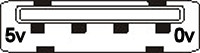
Fig. 5 USB type A socket (viewed from mating side). 

USB LED Powered Base Internals

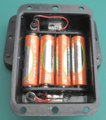
Fig. 6 The layout of the internal components

Results using flexible gooseneck LED lighting

 
The flexible gooseneck LED lights were tried with both stereo and compound microscopes. The beam diameter is wide enough to provide even illumination over the whole field of view at powers above 2x, using just one light. Using both lights provides flexibility in removing shadows. Figure 7 shows the lights in use with a stereo microscope and figure 8 shows results when used with a compound microscope. Figure 9 shows the relative brightness of the 25000mCd LED (left) compared the 8000mCd LED and also some fluorescence of the patterns below the hologram on a £20 note using the 395nm near-UV LED. The 'denomination' text on £5, £10 and £20 notes is designed to fluoresce red and green under 365nm, but this effect was not visible using 395nm. The 25000mCd is my preferred LED for illumination but the beam pattern does include some more yellow and blue patches which may not be ideal for viewing a plain object.


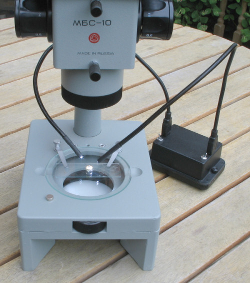
Fig. 7 LED illumination used with a stereo microscope

CD Pits 40X

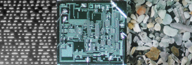
Fig. 8 The pits of a CD viewed through a 40x objective, an AD549 OP-AMP die and a foram strew through a 2.5X objective. 


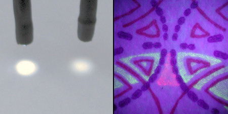
Fig. 9 Comparison of 25000mCd white LED (left) with 8000mCd LED & flourescence of £20 note printing under 395nm near-UV illumination.


All comments to the author Andrew Entwistle are welcomed.


  Microscopy UK Front Page
Micscape Magazine
Article Library


© Microscopy UK or their contributors.

Published in the June 2006 edition of Micscape Magazine.

Please report any Web problems or offer general comments to the Micscape Editor .

Micscape is the on-line monthly magazine of the Microscopy UK website at Microscopy-UK  


© Onview.net Ltd, Microscopy-UK, and all contributors 1995 onwards. All rights reserved. Main site is at www.microscopy-uk.org.uk .